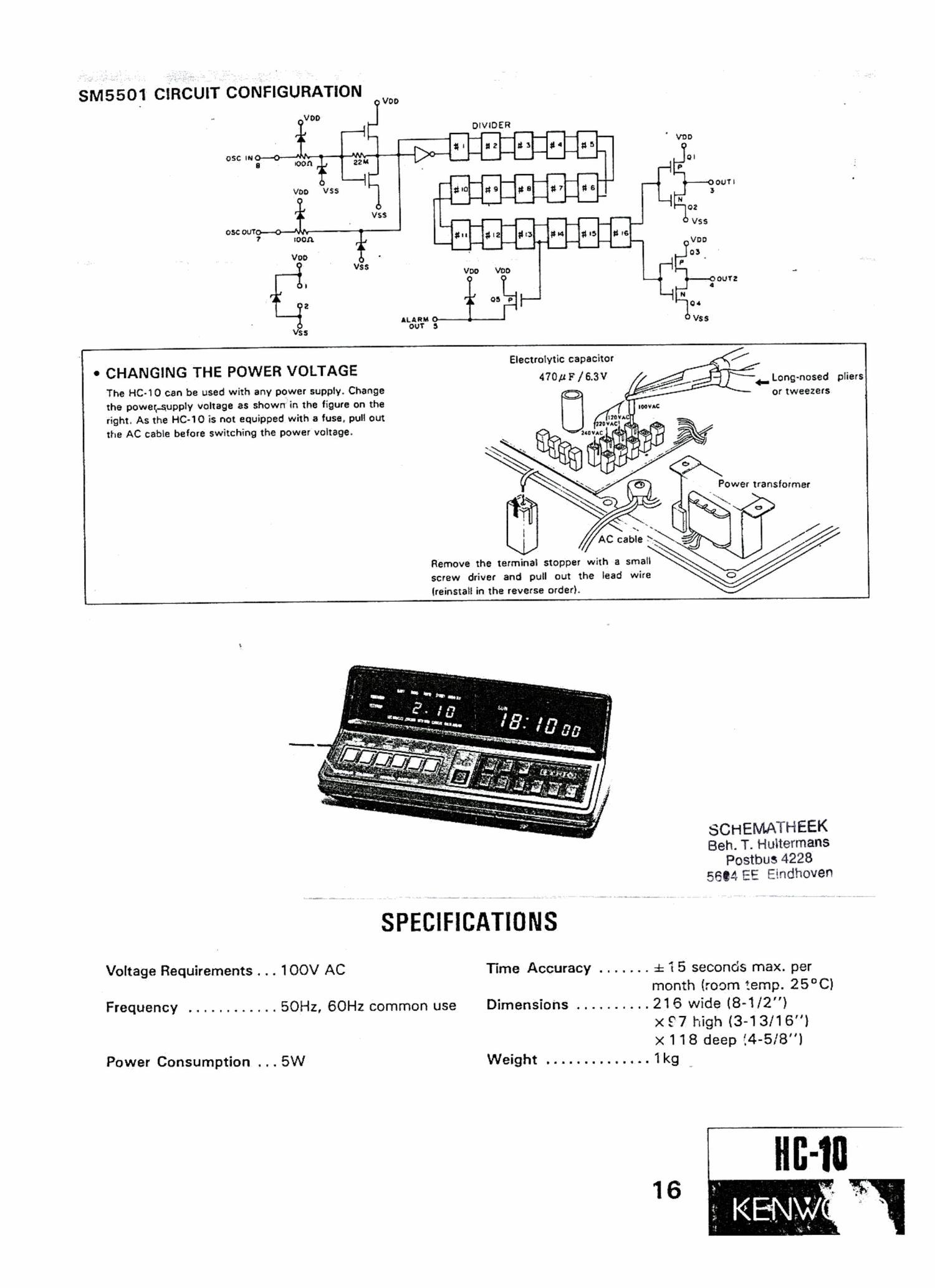
Kenwood HC 10 Schematic

This is the 4 pages manual for Kenwood HC 10 Schematic.
Read or download the pdf for free. If you want to contribute, please mail your pdfs to info@audioservicemanuals.com.

Page: 1 / 4
left right
Kenwood HC 10 Schematic

Extracted text from Kenwood HC 10 Schematic (Ocr-read)


Page 1

SM5501 CIRCUIT CONFIGURATION

~ V00
DIVIDER
W0
13 I2 83 1a 355
DI
P
am no 5: g7 g5 3outl
. _ N
Vss 02
oscour V55
7 roon 1" 8'2 #3 9'4 11-5 the

.__i V Voo V00
I L
a as a [--
ALARM I
:i out 3
ss

Electrolytic capacitor
470 p F / 6.3V


0 CHANGING THE POWER VOLTAGE

The HC-10 can be used with any power supply. Change
the powetAupply voltage as shown in the figure on the
right. As the HC-10 is not equipped with a fuse, pull out
the AC cable before switching the power voltage.

_ Long-nosed plIers
or tweezers

Remove the terminal stopper with a small
screw driver and pull out the lead wire
(reinstall in the reverse order).

SCHEMATHEEK
Beh. T. Huitermans
Postbus 4228
5604 EE Eindhoven

SPECIFICATIONS

Voltage Requirements . . . 100V AC Time Accuracy ....... £15 seconds max. per
month (room temp. 25°C)
Frequency ............ SOHz, 60Hz common use Dimensions .......... 216 wide (8-1/2")

x 97 high (3-13/16)
x 118 deep {4-5I8l
Power Consumption . . . 5W Weight . ........ . . . . . 1kg

16