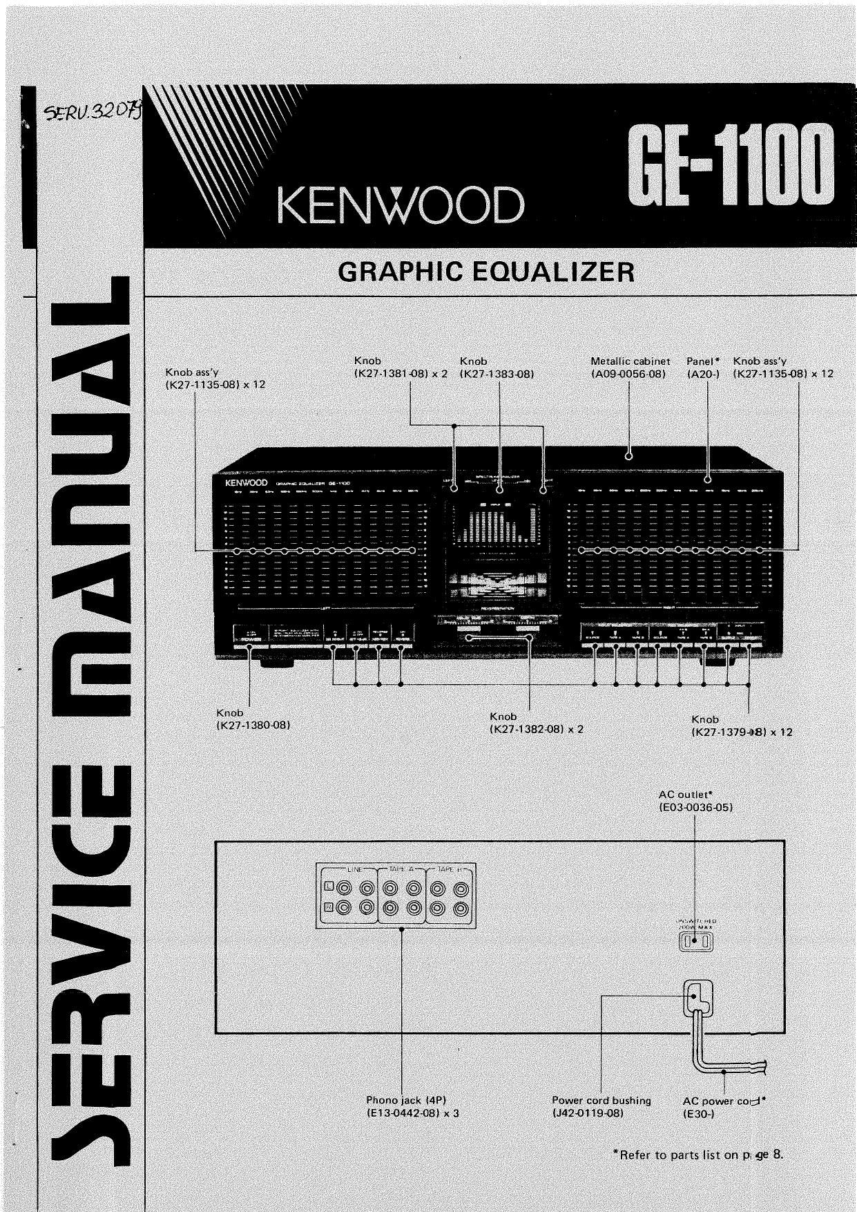
Kenwood GE 1100 Service Manual

This is the 16 pages manual for Kenwood GE 1100 Service Manual.
Read or download the pdf for free. If you want to contribute, please mail your pdfs to info@audioservicemanuals.com.

Page: 1 / 16
left right
Kenwood GE 1100 Service Manual

Extracted text from Kenwood GE 1100 Service Manual (Ocr-read)


Page 2

BLOCK DIAGRAM/CIRCUIT DESCRIPTION

l_______


YIME .
veto:

SPEC"! UM ANALI ZER
it: 2/2
YUTAL

aa~m s

scat-1cm m


ASE

9n
smsTEn

«not 2/: aloe-4n

_°"L'° 523
LIKE OUT

TAPE A nEc

otvaAv F L MEMRUM
coMTnoL omvEn mnuan

|ND|CATOR

TAPE 5 REE

lot-Iain

or 2 1,7

CLOCK CLOGK GATE
oEuEnAren coumol CDNYRDL

l
I;
_ll

l__

vmwynm

Name Function Description
01.2 Clock generator
03~15 Spectrum analizer display control Transistor switch for signal selection
0101.102 Clock generator
0103,104 Sampling hold
0105 Buffer
0106 Muting
0107 Phase shifter I
0108 Reverberetion graphic lamp switch l
0109~11 1 Reverberation graphic lamp driver
0501 ~504 AVFl
0505506 Muting relay driver
lC1 Mixing amp, audio filter
IC2 Total amp For spectrum analizer total stage.
|C3~5 Spectrum analizer audio filter 16. 32, 64,125,250,500,1k, 2k,4k, 8k, 16k and 32k filters.
IC6 Clock counter (4 bit binary counter) Forms a scale of 13 counter together with ICI
[C7 Clock counter (4 to 16 line decoder) Forms a scale of 13 counter together with 1C6.
Output 16 Signals according to scale of 13 counter output.
lC8~10 Spectrum analizer gate control Controls the fluorescent display tube gates according to [(37 output.
' . t Controls the rids of di la tube aocord'n to the ut ut e .
1C1 1~13 Spectrum anallzer FLdnver (10 steps ; -2:,-18,-15fp-1y2, _9 -6, -310? 3 $510 P l vel
1C1 01 AGC amplifier of reverberation graphic
IC102. 103 BED
IC104 Filter
lC105 Amp 7 *
IC201 OP Amp
lC202~206 Frequency resonator Resonating circuits for 12 frequencies between 16H: ant 32kHz.