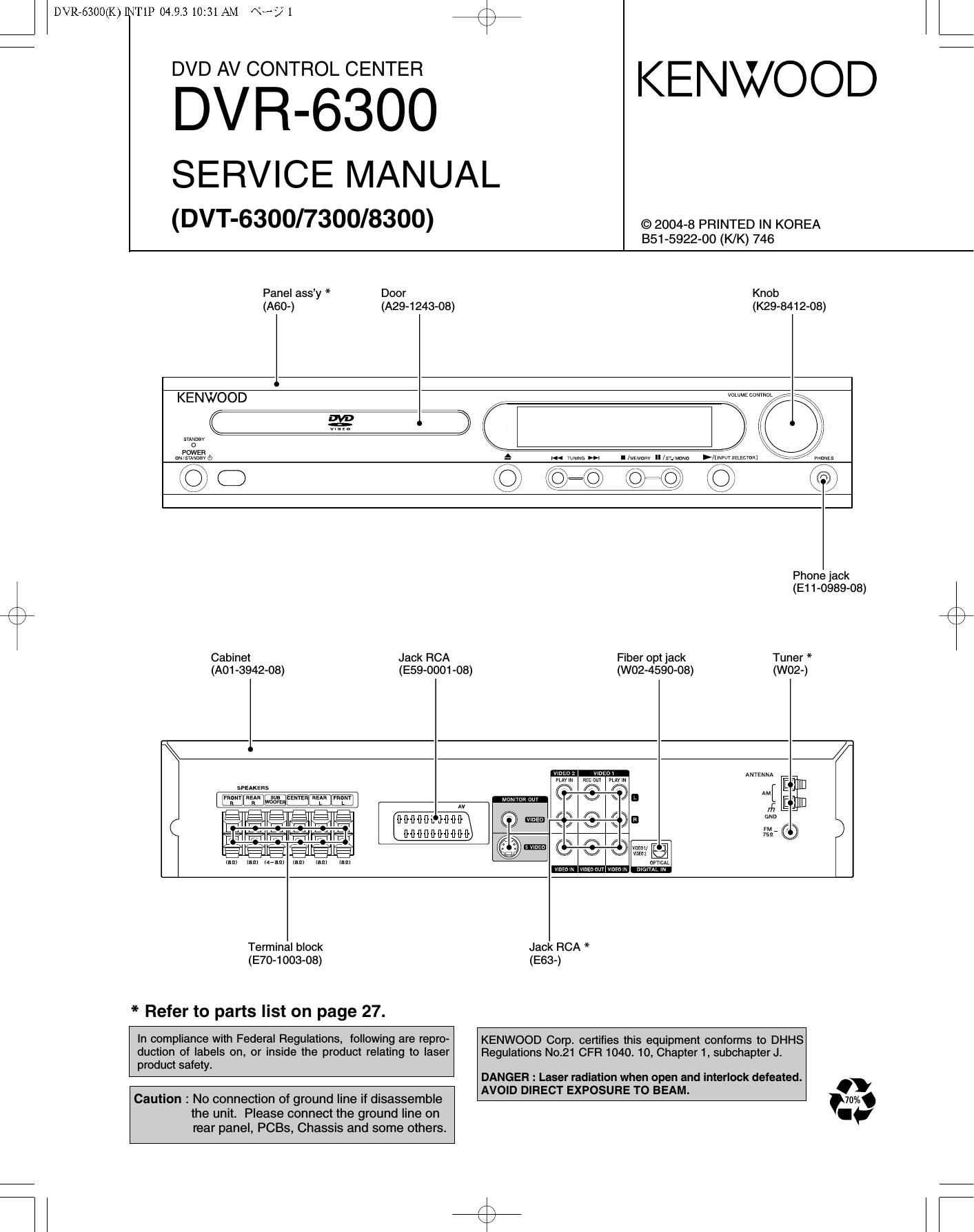
Kenwood DVR 6300 Service Manual

This is the 26 pages manual for Kenwood DVR 6300 Service Manual.
Read or download the pdf for free. If you want to contribute, please mail your pdfs to info@audioservicemanuals.com.

Page: 1 / 26
left right
Kenwood DVR 6300 Service Manual

Extracted text from Kenwood DVR 6300 Service Manual (Ocr-read)


Page 2

DVR76300(K)]INT1P 04.9.3 10:31 AM Nb? 2 / \

DVR-63OO

CONTENTS / ACCESSORIES / CAUTIONS

CONTENTS

CONTENTS / ACCESSORIES / CAUTIONS ............... 2 EXPLODED VIEW ..................................................... 25
PARTS DESCRIPTIONS ............................................. 3 PARTS LIST ............................................................... 27
PC BOARD .................... SPECIFICATIONS ..................................................... 34


SCHEMATIC DIAGRAM

ACCESSORIES
/

FM indoor antenna (1) 7

(For U.S.A.. Canada
and Australia)
(T90-0915-08)

. r: _/_\

Loop antenna (1)
(T90-0917-08)

Accessories tor speaker part

(For DVT-6300 and DVT-7300)

(ForEurope)
Speaker cords (6) *

(T90-0916-08)

Length


@ For Front (2) 4.5 m (177-3/16")
ForCenler (1) 3 m (118-1/8")
For Rear(2) a m (314-15/16")

ForSubwooler(1) 4.5m(177-3/16")

Video cord (Yellow)(1)
(E30-7341-08)

Batteries
(Ros/AAA) (2)

Remote control unit (1)
(A70-1685-08)
Cushion (15) *
(Small : 11 pcs 1 sheet) (Big : 4 pcs 1 sheet)
s e.
M \

it 9/

* See speakers manual.

SYSTEM CONFIGURATIONS

SYSTEM RECEIVER SPEAKER SPEAKER
DVT-6300-H DVR-6300 KSW-6300-H -
I \ DVT-6300-S DVR-Gaoo KSW-6300-S -
s / DVT-7300 DVR-6300 KSW-7300 -
DVT-8300 DVR-Gaoo KS-908HT SW-18HT
CAUTIONS
Operation to reset Note related to transportation and movement

The microprocessor may fall into malfunction
(impossibility to operate erroneous display, etc.)
when the power cord is unplugged while power is
ON or due to an external Iactor.

In this case, switch off the power, wait for several

For the U. 5.,4.

seconds, and then switch the power on again.

CAUTION:

Use ol controls or adjustments or periormenoe oi procedures
other then those specified herein may result in hazardous redis-
tion exposure.

in compliance with Federal Regulations. thetollowing are repro-

ductionsollabalaan. or insidethe productrelntinoto Ileerprad-
ucl surety.

r
r 2957-3. ISHIKAWA-CHO.
1 HACHIOJl-SHI.

r

ToKvO. JAPAN

Location: Back Panel

Belore transporting or moving this unit, carry out the
lollowing operations,
1. Set the POWER ONIOFF switch to the ON
without loading a disc,
2. Wait a Iew seconds and verify that the display
shown appears.

"N0 DISC"

3. Set the POWER ONIOFF switch to OFF.

For (he U.5.A.

Caution on condensation

Condensation (otdew) mayoccur lnsidethe unitwhen there is a great
dmerence intempetature between this unitanothe outside. This unit
may not Iunction property it condensation occurs. In this case. leave
the unrttor a lew hours and restarlthe operation atterlhe condense»
tion has dried up.

Be specially cautious againstcondensation in the iollowing circum-
stances:

When this unit is carried lrom one place to another across a large
dinerenoe in temperature. when the humidity in the room where
this unit is Installed increases. etc.

Note to CATV system installer

This reminder is provided to call the CATV system inetEIIIar'e at-
tention to Article 8211-40 at the NEC that provides guidelines (or
proper grounding and. in particular. speoilies that the cable
ground shell oe connected tothegrounding system orthe build-
ing, as close to the point ol cable entry as practical.

For Canada

NOTICE: This Class B digital apparatus complies with
Canadian ICES-003.

The mar/(I779 ofproaucls using lasers
{Far countries DIflEI man ll.5.A. and Canada)

CLASS I
LASER PRODUCT

The marking this product has oeen classitlsd as close t it
means that there is no danger oi hazardous radiation outside
the product,

Location: Back panel

Page 3

DVR76300(K)]NT1P 04.9.3 10:31 AM \°~/° 3

DVR-63OO

PARTS DESCRIPTIONS

CAPACITORS go 4;) m m g) g 0045 Color* ' Capacitor value
1 2 3 4 5 6 010:1pF _22pF
1 = Type ceramic, electrolytic, etc. 4 = Voltage rating 100 = 10pF
2 = Shape round, square, ect. 5 = Value 101 =100pF Multiplier
3 = Temp. coefficient 6 = Tolerance 102 : 1000pF = 0.001uF 2nd number
103:0-0111': 1st number
- Temperature coefficient
1st Word C L P R S T U 2nd Word G H J K L
Color* Black Red Orange Yellow Green Blue Violet ppm/°C :30 :60 :120 :250 :500
ppm/°C 0 -80 -150 220 -330 -47O -750 Example : CC45TH = ~47O : 60ppml°C
- Tolerance (More than 10pF) (Less than 10pF)
Code C D G J K M X Z P No code Code B C D F G
(%) :0.25 :05 :2 :5 :10 :20 +40 +80 +100 More than 10uF- 10 ~ +50 (pF) :0.1 :0.25 :0.5 :1 :2
-20 -20 -0 Less than 4.7uF -10 ~ +75
- Voltage rating
2 d d
" M" A B c D E F G H J K v
1st word
0 1.0 1.25 1.6 2.0 2.5 3.15 4.0 5.0 6.3 8.0 -
1 10 12.5 16 20 25 31.5 40 50 63 80 35
2 100 125 160 200 250 315 400 500 630 800 -
3 1000 1250 1600 2000 2500 3150 4000 5000 6300 8000 -
C: ' Chip capacitors Dimension (Chip capacitors)
(EX) CC73 F SL1 H 000 J Dimensioncode L W T
l:| l:| l:| l:l l:| l:| Refer to the table above. Empty 5.6 + 0'5 50 + 05 Less than 2'0
1 2 3 4 5 6 7 7 7
4 1 : Type A 4.5 : 0.5 3.2 : 04 Less than 2.0
(Ch'pXCHY RH UJ' 3L) 2 = Shape B 4.5 : 0.5 2.0 1 0.3 Less than 2.0
3 : Dimension C 4.5 : 0.5 1.25 : 0.2 Less than 125
(EX) CK73F F1H000Z ..
l:| l:| l:| l:l :I :I 4:Temp.coeffic1ent D 3.2 :04 25:03 Less than 1.5
1 2 3 4 5 6 7 5 =Voltage rating E 3.2 : 0.2 1.6:0.2 Less than 1.25
(Chip)(B, F) 6 : Value F 2.0 : 0.3 1.25 : 0.2 Less than 1.25
7 : Tolerance G 1.6 : 0.2 0.8 : 0.2 Less than 1.0
RESISTORS
- Chip resistor (Carbon) Dimension
L
(EX) RK73E B2BOOOJ IT
l:l l:l l:l l:l l:l l:l l:l
1 2 3 4 5 6 7
Chi B.F
( PX ) 1T1
- Carbon resistor (Normal type) Dimension (Chip resistor)
EX RD 1 4 B B 2 C 000 J Dimensioncode L W T
( ) l:ll:ll:ll:ll:ll:ll:l E 32:02 16102 1-0
1 2 3 4 5 6 7 F 2.0:0.3 1.25:0.2 1.0
1 = Type 5 : Rating wattage G 16:02 08:02 05:01
2 = Shape 6 : Value
3 = Dimension ' ' 7 = Tolerance Rating wattage
4 = Temp. coeffncnent Code Wattage Code Wattage Code Wattage
1J 1/16W 20 WSW 3A 1W
2A 1/10W 2E 1/4W 3D 2W
2B 1/8W 2H 1/2W