Kenwood DVFS 3100 Service Manual

This is the 34 pages manual for Kenwood DVFS 3100 Service Manual.
Read or download the pdf for free. If you want to contribute, please mail your pdfs to info@audioservicemanuals.com.

Page: 1 / 34
left right
Kenwood DVFS 3100 Service Manual

Extracted text from Kenwood DVFS 3100 Service Manual (Ocr-read)


Page 1

DVF73080(K)]NT1P 04.4.12 9:53 AM \°-A/1

DVD/VCD/CD PLAYER

DVF-3080-S/8100

SERVICE MANUAL

TENTATIVE

© 2004-4 PRINTED IN KOREA
B51-5894-00 (K/K) 1360

KENWOOD

I L

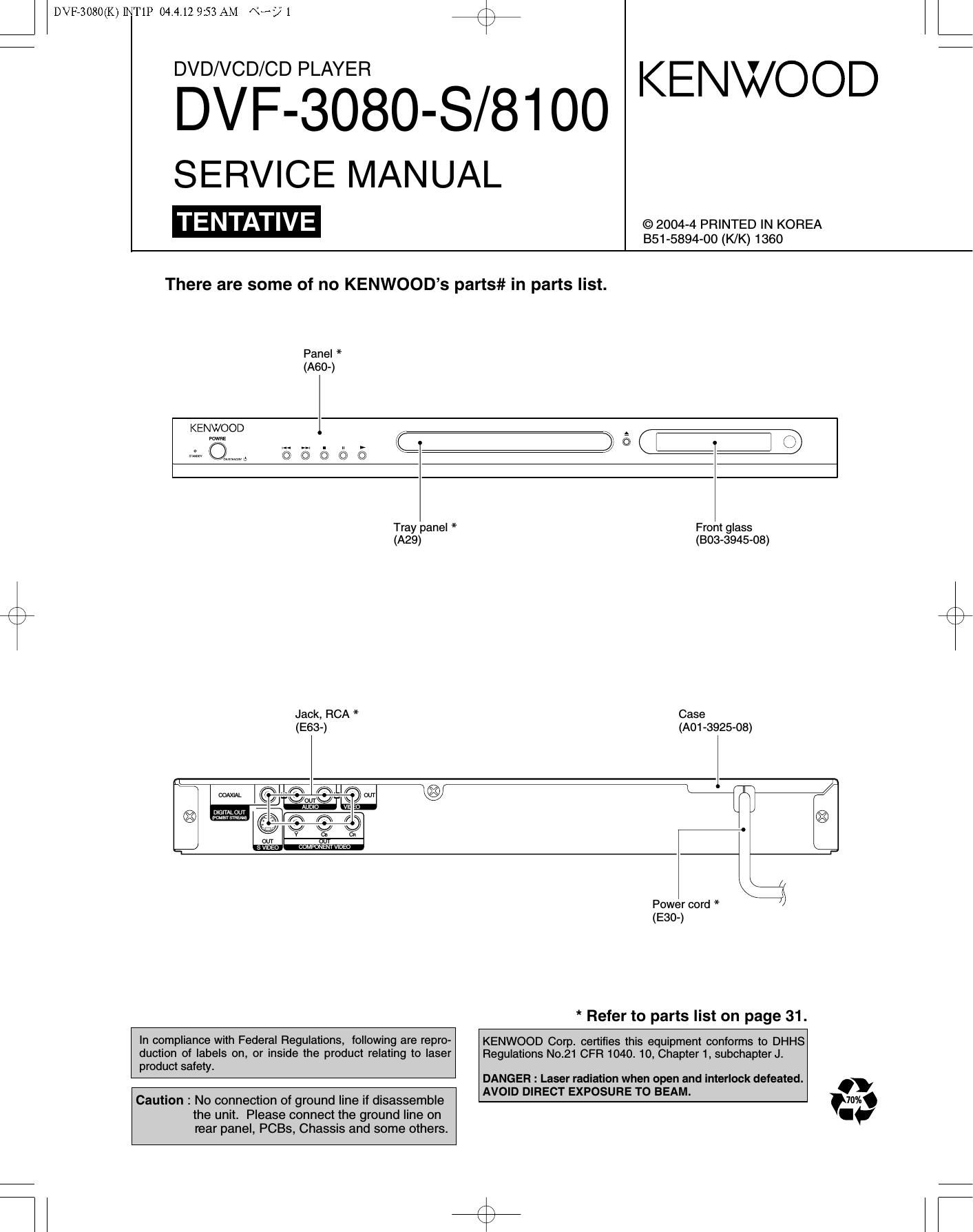
There are some of no KENWOODs parts# in parts list.

Panel *
(A60-)

KENWOOD I,

Fawn:

\KJ/

m

Tray panel * Front glass
(A29) (303-3945-08)
Jack, RCA * Case
(E63-) (AO1-3925-08)
l l /
mm lim flLI Kr? W 23 gfl-/
u

divwvr§

x gems? _, ; ,
O @e e 0 ®
v u an
M COMPONENIVIDED
\j
Power cord * /
(E30-)
* Refer to parts list on page 31.
In compliance with Federal Regulations, following are repro- KENWOOD Corp. certifies this equipment conforms to DHHS
duction of labels on, or inside the product relating to laser Regulations N021 CFR 1040. 10, Chapter 1, subchapter J.
product safety
DANGEFI : Laser radiation when open and interlock defeated.
. . . . . AVOID DIFIECT EXPOSURE TO BEAM. .
Caution : No connection of ground line If disassemble m.

the unit. Please connect the ground line on
rear panel, PCBs, Chassis and some others

Page 2

DVF73080(K)]NT1P 04.4.12 9:53 AM «3? Z

DVF-3080-S/81OO

ACCESSORIES / CAUTIONS

Accessories

Please confirm that the following accessories are present.
Video cable(Yellow) ...(1)

Audio cord (Red. White) ...(1)

Remote control unit ...(1)
(A70-1660-08)

(o

Coaxial cable (Black) ...(1)

...(2)

Cautions

Operation to reset

The microprocessor may fall into malfunction (impossibility to operate erroneous display, etc.) when the power cord is
unplugged while power is ON or due to an external factor.
In this case, switch off the power, wait for several seconds, and then switch the power on again.

Note related to transportation and movement
Before transporting or moving this unit, carry out the
following operations.

1. Set the POWER ONIOFF switch to the ON
without loading a disc.

2. Wait a few seconds and verify that the display
shown appears.

"NO DISC"

3. Set the POWER ONIOFF switch to OFF.

Caution on condensation

Condensation (of dew) may occur inside the unit when there is a great
difference in temperature between this unit and the outside. This unit
may not function properly if condensation occurs. In this case, leave
the unit for a few hours and restart the operation after the condensa-
tion has dried up.

Be specially cautious against condensation in the following circum-
stances:

When this unit is carried from one place to another across a large
difference in temperature, when the humidity in the room where
this unit is installed increases, etc.

The marking of products using lasers
(For countries other than U.S.A. and U.S.-Militaly)

CLASS 1

LASER PRODUCT

The marking this product has been classified as Class 1. It
means that there is no danger of hazardous radiation outside
the product.

Location: Back panel

Manufactured under license from Dolby Laboratories.
"Dolby" and the double-D symbol are trademarks of Dolby
Laboratories.

"DTS" and "DTS Digital Out" are reg- "
istered trademarks of Digital Theater dlt
Systems, Inc.

DIGITAL OUT

Page 8

DVF73080(K)]NT1P 04.4.12 9:53 AM «3? 8

DVF-3080-S/81OO

DECK MECHANISM DISASSEMBLY

MAIN BASE


DiSC CLAMP ASSEMBLY
PLATE CLAMP

MAGNET CLAMP

CLAMP UPPER

Fig. 4-1

BASE MAiN

BOTTOM SIDE VIEW

Fig. 4-2

1.Main Base (Fig. 4-1)

1-1. Clamp Assembly Disc

1) Place the Clamp Assembly Disc as Fig. (A)

2) Lift up the Clamp Assembly Disc in direction of
arrow(A).

3) Separate the Clamp Assembly Disc from the Holder
Clamp.

1-1-1. Plate Clamp

1) Turn the Plate Clamp to counterclockwise direction and
then lift up the Plate Clamp.

1-1-2. Magnet Clamp

1-1-3.Clamp Upper

N

. Tray Disc (Fig. 4-2)

1) Insert and push a Driver in the emergency eject
hole(A) at the right side. or put the Driver on the
Lever(B) of the Gear Emergency and pull the Lever(B)
in direction of arrow so that the Tray Disc is ejected
about 15~20mm.

2) Pull the Tray Disc until it is separated from the Base
Main completely.

Page 23

1. POWER(SMPS) CIRCUIT DIAGRAM

VF(+) Power dead

K \
\ J
N WV 17936 III/170 dllNI (HIOSOSHAG I


Please replace a defective power supply unit WIth a new one except fuse. R102 is defective
VF(-) Power dead )
I ' _ ' _ 'r::_: ' _ ' _ ' _ ' _ ' _I mNsmm) N m; m5 ZD102 '5 defectlve
I I m
' 801m moi Rios i gIrIZIsIJ/sscv 4A o 5 DI 7 a 2 may; 33 PIDl
I swam 2 7/2w I > g I sex/2w Erggw 3 e I vr+
+ o a? l cm
=3o°A~o Dc CHE I 22mm I R131 35 2 VP
I I 6;; SE I A22 T sapr/iKv I i 6 PW? 22K : 752:3:
veg RIM mm
| I w 'J l I as? CM) 2 Tia?
I i V. * é :5 0 K I 7 5V
Bum I 7 Bros a 12V
I HEAD Eumw » c122 R s A GND
I (WW) 47uF/50V I o I By
8 M II I av
' I I910 ' 2 my
I RLIKNF C104 3 D GND
A l «hr/50v I sv
I I o g l7 , iis M 6ND
CH2
I DRAIN DRAIN DRAIN I l a: IYI away
7 , I EIOQ
I ICIOI rmmtsvflIgI; I iououF/isv 3 cm E3 one
D B
I A 6 STARTUP . , vcc 7 I 0 i0 I 52 I Uprzpwu incur/l6 hum/lav
Feirchild ][| pm I JL7 4
EUDIW IN
I
ocP Fa GND I may 7 .
f '\ I I H mu 3 R13
x mm 2 o lUUIijs/Ilsm Q 473 my D: 3.3V, 1.8V, 8V, 12V Power dead
I . .
CIOI 0.022» cus I 59 E smur/ in? I 2 I IC105 lS defectlve
I o Iu/2sov HF/50X 0 i 2 (Nauru) 1 L103 Vccg 5ND RE
A m ' >1 ng . min I W
' I u Vch
I I M2" 47DuF/25V CI 05 M
30 :3 one '1 g
' 0103 7, 7 :3 AN80T54
I A I 1 013; (mg; 7 I??? l IDOI g Vcc3 CTL u IL 7.
I W a I am - I I K N.C REGZ REG REG}
svcssm l I . I L _I 5 5 3 5
I c124 '
RI 0 O
I 3§ rm f}? I L 7 Jen J
is 7
k: A 1 CIZS I
I I nor I was sex/Ix 2: loch/Isv m m
I §§ lGA/ZSOV I I l DEN | m7 ZZUuF/Isv
fig fl mg; msL 7 J U
I V» | 2 1K
v mu
3 I (E g l we ma W =3 om <
| I I w I -n
. Pwml I IgI/gIr ma x2) 5I I511, aEmmi/lav I
3
I BK w» I (mam) icioa ask/w w
RI
I A V I 3 220 W 5V Power dead 0
(Hum) , _ .
in 0107 Is defectlve m
I cus | :7; mos O
GBWF KTCSIS
' ' '1}? I
| l U)
----------------- - m \
"DESI A mgmmmmflwm NOTES= + SWW'E'WMCW CAUTION: For continued safety, replace safety critical components only with man- The DC voltage is an actual reading mea- m
maxim #7 Swimwemsbcnhasslsswnfl. ufacturer's recommended parts (refer to parts list). A indicates safety critical com- sured with a high impedance type voltmeter -L
ponents. For continued protection against risk of fire, replace only with same type with no signal input. The measurement 0
m an rain use s. 0 re uce e ris o ee ric 5 oc , ea a e-curren or resis- va ue ma va 9 en in on e measur-
d t f T d th k I I at h k | k t | cl d th
co

tance measurements shall be carried out (exposed parts are acceptably insulated ing instruments used or on the product.
from the supply circuit) before the appliance is returned to the customer.

51

TI I lT

Page 34

DVF73080(K)]NT1P 04.4.12 9:54 AM «3? 34

DVF-3080-S/81OO

PARTS LIST/SPECIFICATIONS

PARTS LIST
How 70 READ THE PARTS LIST

ABBRE VIA 770/v 0F MODEL AND MASS PRUDl/Cfla/lls DES 77/l/A 770NS

Australia Canada China Eng/and Europe Germany K area Malaysia
MODEL ABE.
X P - - E - - -
DVF-3080-S 3 X P3 - - E3 - - -
DI/F-5700 8 - P8 - - E8 - - -
Mexico PX/AAFES Russia Scandinavia Shanghai USA Ollier area
MODEL ABE.
. y . . - /( -
DVF-Jasfl-S 3 - Y - - - K3 - -
DVF-amo 8 - - - - » K8 - -
SPECIFICATIONS
[Type] [Video Section]
System ....................... DVD video player Video output format ......................................... NTSC/PAL
Signal read system .. Semiconductor laser Video compression
DVD ................................................................... MPEG-2

[D/A Conversion Section]
D/A conversion .. 24 Bit
Oversampling 8 fs (Sampling frequency; 44.1, 48 kHz)
......................... 4 fs (Sampling frequency; 96 kHz)

[Audio section]
Frequency response
Sampling frequency ; 44.1 kHz .
Sampling frequency ; 48 kHz .
Sampling frequency ; 96 kHz .
Signal to noise ratio
Dynamic range ......
Total harmonic distortion .
Channel separation ..
Wow and flutter

8 Hz ~ 20 kHz
. 8 Hz ~ 22 kHz

8 Hz ~ 44 kHz
. More than 100 dB
More than 92 dB
.. Less than 0.007 % (1 kHz)
More than 90 dB (1 kHz)
Below measurable limit

Analog output level/impedance ..................... 2 V l 550 9
Digital output level/impedance
COAXIAL... ..... 0.5 Vp-p/75 Q

OPTICAL (Only DVF-0100 for Europe)
............. -21 dBm ~ -15 dBm (Wave length 660 nm)

Composite video output level
...................... 1 Vp-p (75 9 load, sync. negative)
S-video output level (Except for Europe)

(Y-signal) .............. 1 Vp-p (75 9 load, sync. negative)
(C-signal)
NTSC .. 0.286 Vp-p (75 9)
PAL. 0.300 Vp-p (75 9)
Component Video output level
(Y-signal) 1 Vp-p (75 Q)
(Cb-signal) .. 0.7 Vp-p (75 Q)
(Cr-signal)... 0.7 Vp-p (75 S1)

RGB output level (SCAFlT) (For Europe) ..... 0.7 Vp-p (75 9)
Horizontal resolution More than 500 lines


Video signal to noise ratio More than 70 dB
[General]

Power consumption .. 12 W

Dimensions W : 440 mm (17-5/16)

H : 44 mm (1-3/4)
D :249 mm (9-13/16)
Weight (net)
(DVF-3080) ..
(DVF-8100)..

.. 2.2 kg (4.9 lb)
2.3 kg (5.1 lb)

(a KENWOOD follows a policy of continuous advancements in development. For this reason specifications may
Note

be changed without notice.

0 Sufficient performance may not be exhibited at extremely cold locations (Where water freezes).

a;