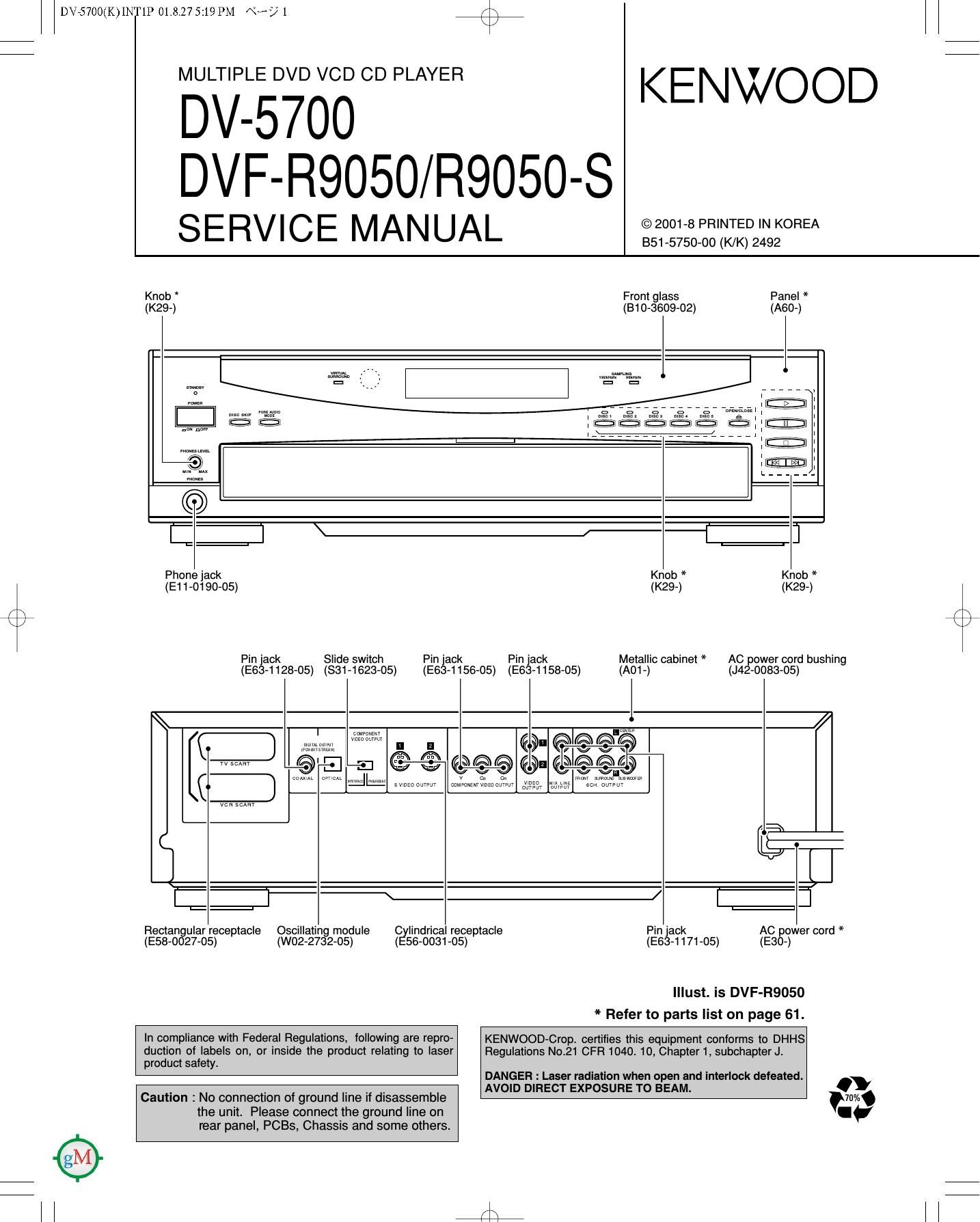
Kenwood DVFR 9050 Service Manual

This is the 61 pages manual for Kenwood DVFR 9050 Service Manual.
Read or download the pdf for free. If you want to contribute, please mail your pdfs to info@audioservicemanuals.com.

Page: 1 / 61
left right
Kenwood DVFR 9050 Service Manual

Extracted text from Kenwood DVFR 9050 Service Manual (Ocr-read)


Page 1

DV75700(K)INT1P 01.817519 PM NH? 1

MULTIPLE DVD VCD CD PLAYER

DV-57OO

+
KENWOOD

DVF-R9050/R9050-S

SERVICE MANUAL

©2001-8 PRINTED IN KOREA
351-5750-00 (K/K) 2492

Knob *
(K29-)

Panel *
(A60-)

Front glass
(B10-3609-02)

Phone jack
(E11-0190-05)

r\
\/

Slide switch

Pin jack
(831-1623-05)

(E63-1128-05)

Pin jack
(E63-1156-05)

Knob *
(K29-)

Knob *
(K29-)

Metallic cabinet *
(A01 -)

Pin 'ack

(E633 1158 05) AC power cord bushing

(J42-0083-05)

mmw
v 220 arw'

co

5 mzaaum

eeo on elem

somtzwmzamm

@- @IED @® I

m ouwur

mm m. .
cum om

vca sum

L==._l

Rectangular receptacle
(E58-0027-05)

Oscillating module
(W02-2732-05)

Cylindrical receptacle
(E56-0031-05)

Pin jack
(E63-1171-05)

AC power cord *
(E3o-)

Illust. is DVF-R9050
* Refer to parts list on page 61.

In compliance with Federal Regulations, following are repro-
duction of labels on, or inside the product relating to laser
product safety.

KENWOOD-Crop. certifies this equipment conforms to DHHS
Regulations No.21 CFR 1040. 10, Chapter 1, subchapter J.

DANGER : Laser radiation when open and interlock defeated.

Caution : No connection of ground line if disassemble
the unit. Please connect the ground line on
rear panel, PCBs, Chassis and some others.

AVOID DIRECT EXPOSURE TO BEAM.

Page 2

DV75700(K)INT1P 01.817519 PM «5? 2

/\
\/

DV-5700/DVF-R9050/R9050-S

CONTENTS / ACCESSORIES / CAUTIONS

Contents

CONTENTS / ACCESSORIES / CAUTIONS...
DISASSEMBLY FOR REPAIR ......
BLOCK DIAGRAM
CIRCUIT DESCRIPTION.


22

PARTS DESCRIPTIONS
PC BOARD ..................
SCHEMATIC DIAGRAM ..
EXPLODED VIEW

....28
29
36
.58


MECHANISM DESCRIPTION . PARTS LIST .......... ....6I
ADJUSTMENT ........................... ....26 SPECIFICATIONS ....Back cover
WIRING DIAGRAM ................................................... 27
Accessories
r N
Audio cables (3) Video cable (1) S Video cable(1) Coaxial cable (1)
(an-osos-os) (E30-1427-05) (E30-2956-05) (E30.2365_05)
Joystick remot control unit(1) Batteries (R6/AA)(2)
(A70-1489-05): RC-D0711
<> .5,
Battery cover (A09-1124-08)
\ J
Cautions

The marking of products using lasers
(For countries other than USA, US.-
Military and Canada)

CLASS 1
LASER PRODUCT
The marking this product has been classified as Class

1. It means that there is no danger of hazardous
radiation outside the product.

Location: Back panel

CAUTION
VISIBLE LASER RADIATION

WHEN OPEN. DO NOT
STARE INTO BEAM.

Inside this laser product, a laser diode classified as
Class 2 laser radiation is contained as alerted by the
internal caution label shown above. Do not stare into
beam.

Location: DVD laser pick»up unit cover inside this
product

Page 3

DV75700(K)INT1P 01.8.27 5:19 PM «5? 3 K1

DV-5700/DVF-R9050/R9050-S

DISASSEMBLY FOR REPAIR

1. How to Remove Tray

1. Remove the front panel and flexible cable.
Disassemble the X25, X35 and power supply pcb with
sub chassis if it is a difficult.

2. Push and hold the lever(®)to clockwise and pull out the
tray to frontwards(®) where the hook of tray((3)) meets
with guide(@).

3. Push hooks(®), both sides, inwards and release them
from guides(@).

4. Pull hooks of tray((5)) outwards and remove the tray
upwards((6)).

/'\
6,5;

F\
\/

2. How to Assemble Tray

1. Adjust the position of drive gear as figure((1)). "mum 0"?"
Check traverse unit is at the lowest position. LOADNG " '
2. Load the tray on the loading mechanism.
Check the position where the loading gear(A) is free(®)
3. Meet the hooks with guides and push hooks to load the . \DRWE
334(3)- \ \ , GEAR
. Set the right side hook to loading mechanism(@). '
5. Set the left side hook to loading mechanism with pulling it
outwards((5)).
6. Push the tray backwards([6)).

J;

Page 5

7 DV75700(K)INT1P 01.3.27 5:19 PM «w; 5 #¢_
DV-5700/DVF-R9050/R9050-S

CIRCUIT DESCRIPTION

TEST MODE

This model has 3 kind of test modes; unit inspection, factory test mode. measurement. In this manual. items of repair. test

mode and inspection are available.

Setting

Turn power on with pressing "PAUSE" key. Display shows "TEST".
Turn power on with pressing "DISCt " key. Display shows "INSPECTION".

Cancellation of Setting
Turn power off.

Key vs Function
Keys which described in the following table work as it is.

TEST MODE
Key Mode Display Operation
PLAY - Playback time Disc Playback
A|| segments light a
SKIP-UP STOP Niagara mode a Display shows cyclically by pressing key
Playback time a
SKIP-UP PLAYBACK Playback time Playback next chapter/track #lprogram #

SKIP-DOWN PLAYBACK Playback time

Playback before chapter/track #lprogram #

Stop to operate and return to first step of this

STOP - Time
(3 test mode.
DISCZ PLAYBACK 3:: ON T MUTE Mute works cyclically on or off.
DISCB _ LPF 60k a LPF 110k Speaker protection works cyclically on or off.(Cut-
off freq. Change 60k or 110k)
0/304 - WE'EAQAXVIBEZ WIDE mode changes cyclically WIDE1 or WIDE2.
DISC5 _ SCART RGB a SCART Video signal of SCART changes cyclically
YC a SCART Through RGB(DVD) a Y/C(DVD) a Through(AV1©AV2)
DISC SKIP OK or IC** Self check mode(refer to Servo Error Code)

STOP+DISC1 STOP

Rotary turns clockwise.

STOP+DISCZ STOP

Rotary turns counter clockwise.

S TOP+DIS C3 STO P

Tray opens

S TOP+DIS C4 STOP

Tray closes

Page 7

DV75700(K)INT1P 01.3.27 5:19 PM «as; 7 #4:;
DV-5700/DVF-R9050/R9050-S

CIRCUIT DESCRIPTION

ERROR CODE OF CIRCUIT BY SELF CHECK MODE (TEST MODE)

DEFINITION l CONTENTS CODE | BLOCK | TIMING
ODC{Optical Device Control)
MODiNOTicRCOK No CRCOK signal 0x4303 (ADSC,ODC,disc ,pickup) Read address error at lead in or focus jump.
MAS,ECC,ERR Abnormal ODC ODC ODC No emission OK on disc and host in 5 secs.

ERROR
LAYERicMPiERR Abnormal LAYER in seek mode -
OUTiPBiAREAiNG OUT of PB AREA
DATAiTFLPLAYiNG DATA Track Play
SEEKiNGicHGNV No data caused seek error
UNCORRECTiERR gorgfntrol data by demodulator

(ADSC,ODC,disc ,pickup)

Over data from disc(DVD : 0xFFF)(VCD :
INVALIDicMDiERR Out of secter ID OxD601 00.02.00 |ess)(CD : OXFFF)

No lead-in data by demodulator

UNCORRECTiLEADIN error OxD602 ODC,disc Time over in lead-in.
UNCORRECT, No lead-in data by demodulator
KEYDET error OXDSOS

DEFINITION | CONTENTS | CODE | BLOCK | TIMING
SERVO
TRAYiLOADINGiERR Tray Loading Error. 0x4000 3.50! TRAY DCM,TRAYCTL,T(time out Ssecs)

Mechanism, Motor LSI
ADSC, pickup & DCMiFCONiTflime out Ssecs),
FOCUSSVERR FOCUS Servo Error, 0x4100 actuator, Driver LSI Lock NO, NO of seek.
- , DCM,DMON,T(time out 10
SPlNDLE75VERR Spindle Servo Error. 0x4101 ADSC thgerLSL d'sc secs),Time out of checking
stop,Time out of start to turn.
/\ DSC Disc Motor Error. DCMiDMOFiTOime out 10secs),
\ / Abnormal FG-period in ADSC, Driver LSI, disc DCMiDMMODEiTflime
DSC,DM,ERR DVD, Abnormal turn of 0X4102 Motor out100ms) Abnormal turn of
disc motor, disc motor.,
6626 CLVS Failure. . . .
. . ADSC, Driver LSI, disc DCMiDMOFiTOIme out 10secs)
CDC,CLV,ERR étlsnormal FG-period In 0X4103 Motor Setting abnormal CLV
TRAVERSEiERR Traverse Motor Error. 0x4104 ADSC DJéfgrLS" feed DCMJNNERJuime out 5secs)
. DCMiTRONiTflime out 1sec)

TRACK,SVERR Tracking Servo Error 0x4105 acltLIIDaig lelfingfél Command error,Focus jump

Lock NG (ReSartServo) N6 of

Over 200 seek times

ADSC, pickup &

SEEKiTIMEOUTiERR Seek Time Out Error 0x4106 actuator, Driver LSI

DSC Error ADSC

DSCiERROR (status data error) ERROR ADSC Command error
DSC7NOTREADY DSC Not Ready Error 233ng ADSC ADSC REDY time out
. ADSC Over of CLV OK Over
DSC,TIM,ERR DSC TImeOut Error, ERROR ADSC of command end
DSC Communication ADSC
DSC,COM,ERR Failure. ERROR ADSC No use
. ADSC Error of CD-trick play and CD/DVD
DSC,ATN,ERR DSC Attention Error. ERROR ADSC seek. FC jump in DVD-play.
. No check of media, Error after
INVALlDiMDTYP Out of MedIa 0x4300 ADSC servo retry. Abnormal disc.
6626 QCODE do not Read error in Cue or
DONOTEQREADEERR Read Error. 0X4302 ADSC Rev play of CD
Stop servo operation after setting
DSCiESCAPE DSC Command Escape - ADSC the ESC flug in mode register of
ADSC.
FEP
Adjustment error on data EEP jitter and data slice offset
FEPICERR slice offset ERROR ADSC FEP adjustment error 7