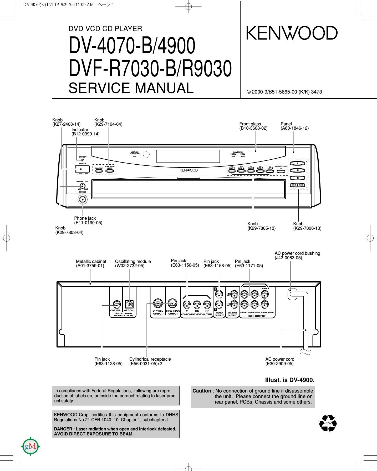
Kenwood DVFR 7030 Service Manual

This is the 43 pages manual for Kenwood DVFR 7030 Service Manual.
Read or download the pdf for free. If you want to contribute, please mail your pdfs to info@audioservicemanuals.com.

Page: 1 / 43
left right
Kenwood DVFR 7030 Service Manual

Extracted text from Kenwood DVFR 7030 Service Manual (Ocr-read)


Page 1

DV4070(K)INT1P 9/30/00 11:00 AM \°-/1 /\
\/

BDllC-XBPiAéE7B/4900 KENWOOD

DVF-R7030-B/ R9030

S E RV I C E MA N UA L © 2000-9/B51-5665-00 (K/K) 3473

Knob Knob
(K27-2408-14) (K29-7194-04) Front glass Panel
Indicator (810-3608-02) (A60-1846-12)

(B1 2-0399-14)

IE
man


.
KENWOOD ,, :
mm .
._. i® :
mum i
l® :
Phonejack
(E11-0190-05) Knob Knob

Knob (K29-7805-13) (K29-7806-13)

(K29-7803-04) 7
/\ / \
k / \

AC power cord bushing
. . . . . . _ _ _ _ (J42-0083-05)
Metallic cabinet Oscnlatlng module Pl lElCk Pin Jack Pin Jack
(A01-3759-01) (W02-2732-05) (E63-1156-05) (E63-1158-05) (E63-1171-05)
I I-fl
cauisa
R R
/ \ '@ e e 6 < t
\ it R R t
©@l w©©©@a©ficeed
mum oMchL StVIDED suszvlnzo v Cb Cr MW": Fugmsuaaguunm-mfl
@flfizfiéflu \°""" °'"""' 00'0"?me 0min omm samuwur
/\-:
Pin jack Cylindrical receptacle AC power cord
(E63-1128-05) (E56-ODS1-05)x2 (E30-2909-05)
Illust. is DV-4900.

In compliance with Federal Regulations, lollowing are repro- Caution : No connection of ground line if disassemble

duction of labels on, or inside the porduct relating to laser prod- the unit. Please connect the ground line on

U0! salety- rear panel, PCBs, Chassis and some others.

KENWOOD-Crop. certifies this equipment conforms to DHHS

Regulations No.21 CFR 1040. 10, Chapter 1, subchapter J. fiW

DANGER : Laser radiation when open and interlock defeated. I.

AVOID DIRECT EXPOSURE TO BEAM.

ll 4 ll

Page 2

r\
\/

DV4070(K)INT1P 9/30/00 11:00 AM \°-/2

DV-4070-B/4900/DVF-R7030-B/R9030

CONTENTS / ACCESSORIES

Contents

CONTENTS / ACCESSORIES ..............
DISASSEMBLY FOR REPAIR
CIRCUIT DESCRIPTION ...........
ADJUSTMENT .................
PARTS DESCRIPTIONS.

PC BOARD ........................
SCHEMATIC DIAGRAM.
EXPLODED VIEW .............
PARTS LIST ....................
SPECIFICATIONS ..........


Note: Please contact our KENWOOD Service Department in your side if you want the information;
Main Microprocessor(MN10102LP25G),Sub Microprocessor(MN101CZBC) ports explanation,
D.R. I.V.E. ]I and SCART Circuit Description and fu|l(previous) format Parts list on this
model. You can be available them by internet from us.

Accessories

r

Joystick remote control unit (1)
(A70-1412-05)

Batteries (R6/AA)(2)

Battery cover(A09-1 124-08)

Audio cables(3)
(E30-0505-05)

Optical fiber cable(1)
(819-1529-05)

Video cable(1)
(E30-1427-05)

AC plug adapter (1)
(E03-0115-05)

7:
$4

Use to adapt the plug on the
power cord to the shape of the
wall outlet.

(Accessory only for regions
where use is necessary.)

lnstructoin manual/
separate User's Guide (1)

S Video cable(1)
(E30-2956-05)

tswmu

Malfunction of Microcomputer

In case the microcomputer malfunctions, making operations
impossible or showing wrong messages on the display even
if you connected everything properly. When the microcom-
puter malfunctions, perform the following procedure to reset
the microcomputer and return it to the normal condition.

1. While holding E on the player main unit,

press @ .

2. The display on the main unit shows blinking "INIT" (ini-
tializing). then shows "INIT 0K!" (Initialization OK) to
indicate that the microcomputer is reset.

3. Press fl on the main unit to turn it off. then press

it again to turn it on.

o The resetting clears the setups stored in the microcom-
puter and returns it to the factory-set initial condition.
After resetting, you should perform the various setups
of the player again from the beginning.

Transport or moving precautions

When transporting or moving the player, first remove the
disc and observe the following procedure.

1. Turn the player power on.

2. Wait for a few seconds, until the display shows "NO
DISC".

3. Turn the player power off by pressing fl .