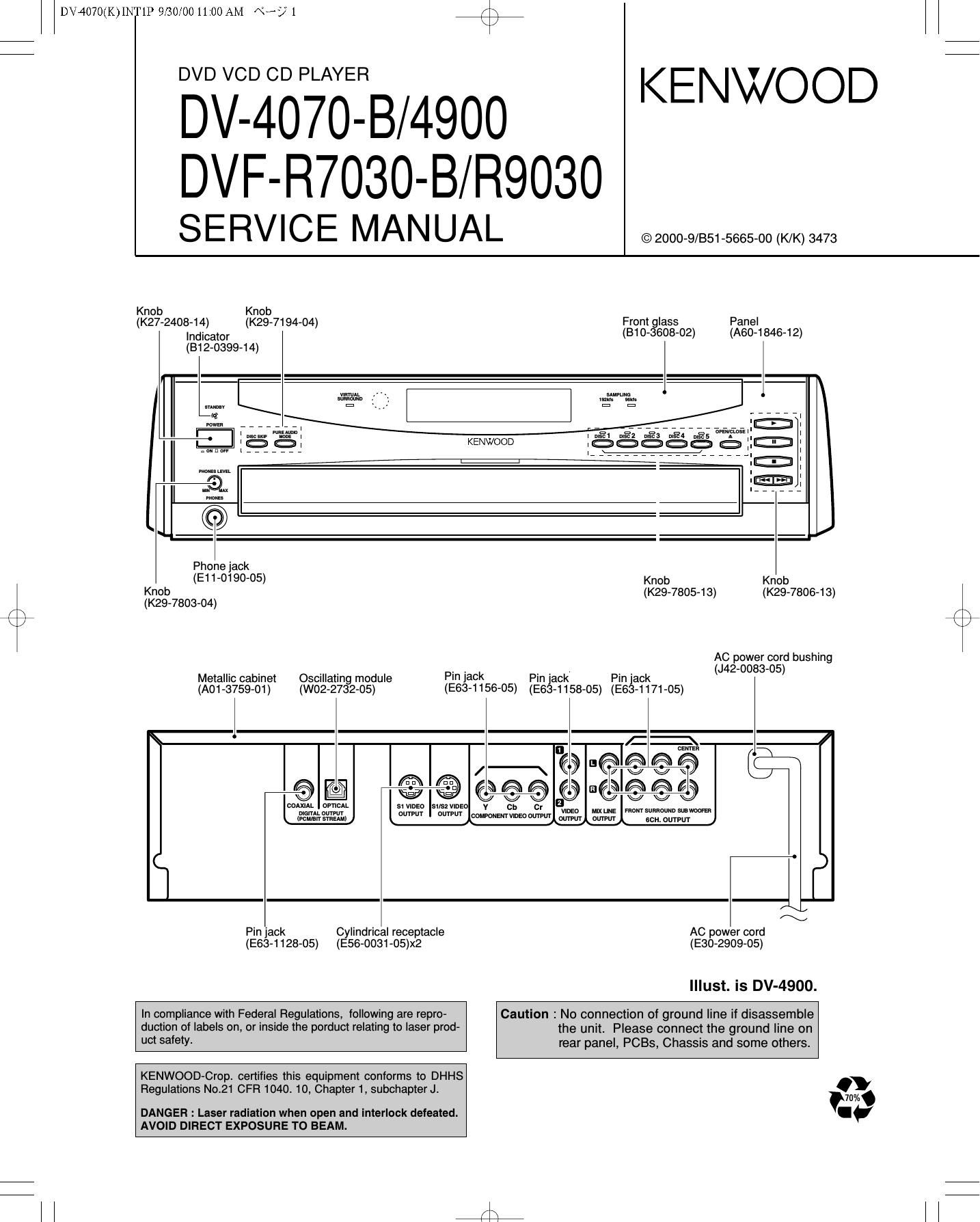
Kenwood DVFR 7030 B Service Manual

This is the 43 pages manual for Kenwood DVFR 7030 B Service Manual.
Read or download the pdf for free. If you want to contribute, please mail your pdfs to info@audioservicemanuals.com.

Page: 1 / 43
left right
Kenwood DVFR 7030 B Service Manual

Extracted text from Kenwood DVFR 7030 B Service Manual (Ocr-read)


Page 1

DV4070(K)INT1P 9/30/00 11:00 AM \°-/ 1

DVD VCD CD PLAYER

/\
\/

KENWOOD

DV-4070-B/4900
DVF-R7030-B/ R9030

SERVICE MANUAL

© 2000-9/851-5665-00 (K/K) 3473

Knob

(K27-2408-1 4)
Indicator
(B1 2-0399-14)

Knob
(K29-7194-04)

Panel
(A60-1846-12)

Front glass
(810-3608-02)

ti
man

.
KENWOOD ; : :
mum .
mm l® :
i® :
Phonejack
(511-0190-05) Knob Knob
$23578 04 (K29-7805-13) (K29-7806-13)
/\ ( - ) /'\
k / \

Metallic cabinet Pi l
(A01 ~3759-01 )

Oscillating module
(W02-2732-05)

(E63-1156-05)

AC power cord bushing
. . . . (J42-0083-05)
ack Pin Jack Pin Jack

(E63-1158-05) (E63-1171-05)

[-
fl / \ -o'ooo @o
fl @l e e oeopmoooo

OOAXIAL omen
nioerLouvPIn
woman menu

51 wuss

oumn omPur

susz VIDEO


Cylindrical receptacle

Pin jack
(E56-ODa1-05)x2

(E63-1128-05)

AC power cord
(E30-2909-05)

Illust. is DV-4900.

In compliance with Federal Regulations, lollowing are repro-
duction of labels on, or inside the porduct relating to laser prod-
uct safety.

Caution : No connection of ground line if disassemble
the unit. Please connect the ground line on
rear panel, PCBs, Chassis and some others.

KENWOOD-Crop. certifies this equipment conforms to DHHS
Regulations No.21 CFR 1040. 10, Chapter 1, subchapter J.

DANGER : Laser radiation when open and interlock defeated.
AVOID DIRECT EXPOSURE TO BEAM.

4i;

Page 2

r\
\/

DV4070(K)INT1P 9/30/00 11:00 AM \°-/2

DV-4070-B/4900/DVF-R7030-B/R9030

CONTENTS / ACCESSORIES

Contents

CONTENTS / ACCESSORIES ..............
DISASSEMBLY FOR REPAIR
CIRCUIT DESCRIPTION ...........
ADJUSTMENT .................
PARTS DESCRIPTIONS.

PC BOARD ........................
SCHEMATIC DIAGRAM.
EXPLODED VIEW .............
PARTS LIST ....................
SPECIFICATIONS ..........


Note: Please contact our KENWOOD Service Department in your side if you want the information;
Main Microprocessor(MN10102LP25G),Sub Microprocessor(MN101CZBC) ports explanation,
D.R. I.V.E. ]I and SCART Circuit Description and fu|l(previous) format Parts list on this
model. You can be available them by internet from us.

Accessories

r

Joystick remote control unit (1)
(A70-1412-05)

Batteries (R6/AA)(2)

Battery cover(A09-1 124-08)

Audio cables(3)
(E30-0505-05)

Optical fiber cable(1)
(819-1529-05)

Video cable(1)
(E30-1427-05)

AC plug adapter (1)
(E03-0115-05)

7:
$4

Use to adapt the plug on the
power cord to the shape of the
wall outlet.

(Accessory only for regions
where use is necessary.)

lnstructoin manual/
separate User's Guide (1)

S Video cable(1)
(E30-2956-05)

tswmu

Malfunction of Microcomputer

In case the microcomputer malfunctions, making operations
impossible or showing wrong messages on the display even
if you connected everything properly. When the microcom-
puter malfunctions, perform the following procedure to reset
the microcomputer and return it to the normal condition.

1. While holding E on the player main unit,

press @ .

2. The display on the main unit shows blinking "INIT" (ini-
tializing). then shows "INIT 0K!" (Initialization OK) to
indicate that the microcomputer is reset.

3. Press fl on the main unit to turn it off. then press

it again to turn it on.

o The resetting clears the setups stored in the microcom-
puter and returns it to the factory-set initial condition.
After resetting, you should perform the various setups
of the player again from the beginning.

Transport or moving precautions

When transporting or moving the player, first remove the
disc and observe the following procedure.

1. Turn the player power on.

2. Wait for a few seconds, until the display shows "NO
DISC".

3. Turn the player power off by pressing fl .

Page 4

DV4070(K)INT1P 9/30/00 11:00 AM \°-/4 K1

DV-4070-B/4900/DVF-R7030-B/R9030
DISASSEMBLY FOR REPAIR

3. How to Remove Clamper Ass'y 4. How to Disassemble Clamper Ass'y

1. Remove screws.

f Clamper wslghl

6. Tangential and Tilt Adjustment

1. Turn the power on with pressing the DISC 1 key.
(Display shows "INSPECTION"; test mode.)

2. Press the DISCt key in playback mode again.
Display shows "Jitter W %"

3. Turn off if cancel test mode.

5. How to Disassemble Traverse Unit

1. Move the traverse to upward by turning motor pulley
(CD~ (3))-

2. Make the gap between the tray guide and guider(L) with
driver((4))

3. Remove the screws((5), (6)).

F\
\/

Pmlmdlng /"'
pan

Tllt adjustment screw 2
Tm adjustment screw 1

{

HEAR

Change in
jitter value


------ Optimum
point

Adjustment angle

~ Jitter value depends on the model:
(1) If the jitter value changes like A,
the optimum point is easy to find.
(2) If the jitter value changes like B,
4 set the optimum point near the middle.

Page 8

CIR/TESTMODE 9/30/0011:01AM «was #4:;
DV-4070-B/4900/ DVF-R7030-B/ R9030

CIRCUIT DESCRIPTION

Port No. Port Name IIO Description
13 0801 O Clock output
14 V35 0 GND
15 XI | No use
16 XO 0 No use
17 MMOD | GND
18 TXDO O SIOO data output port. Main processor contact.
19 RXDO | SIOO data input port. Main processor contact.
20 SCKO O SIOO clock
21 SB01 O SIO1 data output port. FL driver contact.
22 SB11 | SIO1 data input port. FL driver contact.
23 SCK1 | SIO1 clock
24 FLCE O FL chip enable.
25 RESET | CPU reset.
26 E208 O No use
27 P11 0 No use
28 MECHAVR O Mechanism PCM output.
29 P13 0 No use
30 LED DM 0 No use
31 REMOCON | Remocon code input.
32 P08 SEN O Mecahnism position sensor
33 MEOHA FG | Mecahnism frequency generator(FG) signal input.
34 OPEN SW I Tray open switch sensor.
35 CLOSE SW | Tray close switch sensor.
36 120 SDA O IC4OO control (I2C data). Scart drive/E2ROM
/ \ 37 SB12 O No use
\ 2 38 120 SDC O |2C clock.

39,40 P3334 O No use
41 TM+ O Tray motor positive port.
42 TRM- O Tray/rotary motor common port.
43 RM+ 0 Rotary motor positive port.
44 RGBL O Y signal.
45 AOP 0 Video signal selector. AOP=Pure Audio Mode.
46 YCBH O H=scart color-difference signal. L=RGB.
47 TRAY OPEN 0 No use
48 TRAY CLOSE O No use
49 POWER O H=on. L=power off.
50 FL OFF 0 No use
51 WIDE O H=squeeze. L=|etter box. L=normal.
52 WIDE2 O H=squeeze. H=Ietter box. L=normal.
53 0 OFF 0 C-signal of YC-signal on/off. H=on. L=off.

54-56 P52-54 O No use
57 CE 0 Power chip enable.

58-60 P61 -63 O No use

61-68 LED18-11 O No use
69 POWER LED 0 Power LED(D9).
70 96kHz O 96kHz LED(D7).
71 DISCZ 0 Disc 2 LED(D2).
72 DISC4 O Disc 4 LED(D4).
73 V88 LED 0 Vss LED(DG).
74 AOP LED 0 AOP LED(D15).
75 SHOWER 0 Shower LED(D14).
76 192kHz O 192kHz LED(D8)
77 DISCl 0 Disc 1LED(D1)
78 DISCB O Disc 3 LED(D3).
79 DISCS 0 Disc 5 LED(D5).
80 POWER MUT 0 Power mute. 8

ll 4%.

Page 13

DV4070(K)INT1P 9/30/00 11:00 AM \°-/ 13

DV-4070-B/4900/DVF-R7030-B/R9030

CIRCUIT DESCRIPTION

INSPECTION
Key Mode Display Operation

PLAY - Playback time Disc Playback
All segments light ->

SKIP-UP STOP Niagara modea Display shows cyclically by pressing key
Playback time->

SKIP-UP PLAYBACK Playback time Playback next chapter/track #lprogram #

SKIP-DOWN PLAYBACK Playback time Playback before chapter/track #Iprogram fr

STOP _ INSPECTION stop to-operate and return to first step of this

inspection mode.

STOP STOP Model/destination/re Stop to playback and return to first step of this
gion code test mode.

DISC1 PLAYBACK Jitter 9% Shows jitter value(binary value vs time deviation

of PLL-clock)
DISCZ - CPPM KEY ID 15 figures.
DISC4 WIDE1_>WIDE2 WIDE m d h e |' || WIDE1 WIDE2
' n | I' .
LNORMALJ oecagscyccay o

DISCS _ SCART RGBASCART Video signal of SCART changes cyclically

YC->SCART Through RGB(DVD)->Y/C(DVD)->Through(AV1©AV2)

r\
\/

ERROR CODE OF MECHANISM

DISPLAY CONTENTS REASON CANCELING KEY REMARKS
E1001 No'contact With Main processor doesn t work No
main processor Sio-O bus damaged
N ' ht 't' f t
Poor disc chucking O ",9 p05i '0'? 0 re aw No
E1101 Foreign matter inserted
No cancellation of No right position of rotaiy No
chucking Foreign matter inserted
E1102 No turn of rotary Foreign matter inserted EEIIEN/CLOSE or DISC
E0101 No open Mechanism jam CLOSE Initialization
No Show No Close Mechanism jam Initialization
Disc full load .
E0102 Playing Disc inside Not stop to turn the proper N0 Remove the one dlsc after
. . turn power off
position
L d d' t 't'
No detection of disc 0a , '80 a "°,pr°perp°5' '0" OPEN/CLOSE or DISC Check the sensor of discs on
50703 .. Foreign matter Inserted at
posmon SKIP the rotary.
sensor
No show Waiting Turn power off in open/close CLOSE Press the CLOSE key'after
mode. turn the power on again.

13