Kenwood DVFR 5060 S Service Manual

This is the 24 pages manual for Kenwood DVFR 5060 S Service Manual.
Read or download the pdf for free. If you want to contribute, please mail your pdfs to info@audioservicemanuals.com.

Page: 1 / 24
left right
Kenwood DVFR 5060 S Service Manual

Extracted text from Kenwood DVFR 5060 S Service Manual (Ocr-read)


Page 1

DV605(K) INT1P( 02.7.9326 PM NH? 1

r\
\/

MULTIPLE DVD/VCD/CD PLAYER

DV-605/DVF-R5060-S

/\
\/

SERVICE MANUAL

©2002-7 PRINTED IN KOREA
B51-5802-OO (K/K) 1402

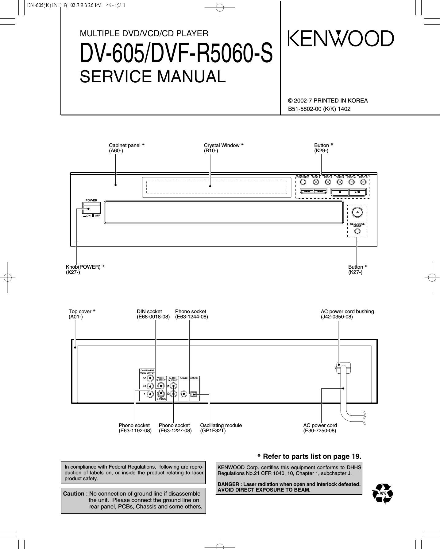
Cabinet panel * Crystal Window * Button *
(A60-) (310-) (K29-)
PowER
* (7?:
-rm 1m l \,/I l
l
l
l
l
l, , , , ,
Knob(POWER) * Button *
(K27-) (K27-)
Top cover * DIN socket Phono socket AC power cord bushing
(A01-) (E68-0018-08) (E63-1244-08) (J42-0350-08)
Q we" tilt. W W I
0 £13 °©
, x \ g
Q Q-Q ©E I
I \\
k /<
Phono socket Phono socket Oscillating module AC power cord \
(E63-1192-08) (E63-1227-08) (GP1F32T) (E30-7250-08)

* Refer to parts list on page 19.

In compliance with Federal Regulations, following are repro-
duction of labels on, or inside the product relating to laser
product safety

KENWOOD Corp. certifies this equipment conforms to DHHS
Regulations N021 CFR 1040. 10, Chapter 1, subchapterJt

DANGER : Laser radiation when open and interlock defeated.

Caution : No connection of ground line it disassemble
the unit. Please connect the ground line on
rear panel, PCBs, Chassis and some others.

AVOID DIRECT EXPOSURE TO BEAM.

KENWOOD

Page 2

DV605(K)INT1P( 02.7.9326 PM «522 /\

DV-605/DVF-R5060-S

CONTENTS / ACCESSORIES / CAUTIONS

Contents

CONTENTS / ACCESSORIES / CAUTIONS... 2 SCHEMATIC DIAGRAM

DISASSEMBLY FOR REPAIR.. .3 EXPLODED VIEW

BLOCK DIAGRAM .4 PARTS LIST .......

ADJUSTMENT ...... ....4 SPECIFICATIONS

PC BOARD ................................................................ 5

Accessofies
Please confirm that the following accessories are present.
Audio video cord (Red, White, Yellow) ...(1) Remote control unit ...(1) Batteries(R6/AA) ...(2) Coaxial cable ...(1)
(E30-2990-08) (A70-1570-08) (E30-7235-08)

r\
\/

Cautions

operation to reset 0 In Power ON condition, keep the DISC 3 key and the H4

The microprocessor may fall into malfunction (impos- (Skip) key pressed at the same time.

SIbIIItY to operate erroneous dismay, etc.) when the 9 When both keys are pressed, the region code of the unit,
Power cord IS unplugged while power IS ON or due to the software version, etc. will be displayed on the dis-
an external factor. In this case, execute the following play. (When nothing is done, the display of this informa-
procedure to reset the microprocessor and return it to tion continues.) Example: 72. 14.02:05

normal condition. 0 Press the DISC 4 key and the K4 key at the same time.

"BYE" will be shown on the display.
0 Press the POWER ON/OFF switch to go to Power OFF.
9 When Power ON is performed with the POWER ON/OFF
switch, the settings become the default factory settings.

0 Please note that resetting the microprocessor clears the
contents stored in, it returns the microprocessor to the con-
dition when it left the factory.

The marking of products using lasers
(For countries other than U.S.A., U.S.-Military and Canada)

CLASS 1

LASER PRODUCT

The marking this product has been classified as Class 1. It
means that there is no danger of hazardous radiation outside
the product.

Location: Back panel