Kenwood DVFK 5020 Service Manual

This is the 80 pages manual for Kenwood DVFK 5020 Service Manual.
Read or download the pdf for free. If you want to contribute, please mail your pdfs to info@audioservicemanuals.com.

Page: 1 / 80
left right
Kenwood DVFK 5020 Service Manual

Extracted text from Kenwood DVFK 5020 Service Manual (Ocr-read)


Page 1

ove3o3/ovpesozmk)COVER1,1P(99.11.210:39AM y [w 1

DVD VCD CD PLAYER

DV-303/DVF-5020/K5020

SERVICE MANUAL

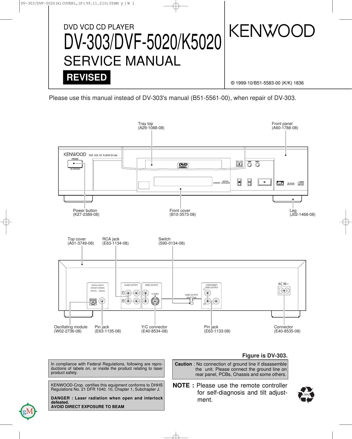
Please use this manual instead of DV-303s manual (851-5561-00), when repair of DV-303.

KENWOOD

© 1999-10/851-5583-00 (K/K) 1836

Tray top
(A29-1088-08)

Front panel
(A60-1788-08)

KENWOOD nvu vcu w pwmvrm

paws:

%

7:1-

HIE

1::1

Power button
(K27-2389-08)

rx
\/

Top cover

FlCA lack
(A01 -3749-08)

(E63-1 134-08)

From cover
(810-3573-08)

Switch
(890-0134-08)

1:];

Leg
(J02-1468-08)

E?

WWW woioouwur
If no a

\ 7 \9 \w svium

mogoo


(mm
mm ourwur
(7
ma ourwr Q J
minim.

AC|N~

EVQ

[2:1

Oscillating module

Pin lack
(W02-2736-08)

(E63-1135-08)

Y/C connector
(E40-8534-08)

1::1

Pin jack
(E63-1133-08)

Figure is DV-303.

In compliance with Federal Regulations, following are repro-
ductions of labels on, or inside the product relating to laser
product safety.

KENWOOD-Crop. certilies this equipment conforms to DHHS
Regulations No 21 DFR 1040. 10, Chapter 1, Subchapter J.

DANGER : Laser radiation when open and interlock
deleated.
AVOID DIRECT EXPOSURE TO BEAM

Caution : No connection of ground line if disassemble
the unit. Please connect the ground line on
rear panel, PCBs, Chassis and some others.

NOTE : Please use the remote controller
for self-diagnosis and tilt adjust-
ment.

Connector
(E40-8535-08)

Page 2

rx
\/

Dvr3o3/DVFR5020Ik)COVER1,1I>(99.11.210:39AM y [w 2 /\

DV-303/DVF-5020/K5020

CONTENTS / ACCESSORIES

Contents
CONTENTS / ACCESSORIES ..... WIRING DIAGRAM ....3o
DISASSEMBLY FOR REPAIR . 3 PC BOARD ............... 32


41
.93

.13 SCHEMATIC DIAGRAM.
.17 EXPLODEDVIEW....

BLOCK DIAGRAM
CIRCUIT DESCRIPTION.

ADJUSTMENT ....... .21 PARTS LIST .......... ....96
ABBREVIATION ..... ....22 SPECIFICATIONS ....BaCk cover
VOLTAGE CHART .................................................... 24

"Disassembly for repair" is for DV-303.

Note: There is different part in this manual as compared with a usual one because we use OEM
tactorys data.

KENWOOD MODEL OEM MODEL

DV-303,DVF-5020 DVD-A120U
DVF-K5020 DVD-A160EN
Accessories
r w
Remote control unit ......... 1 Batteries .................... 2 AC cord ...................... 1
(A70-1353-08): K,K1,Y for remote control unit [size "AA"] (E30-2937-08): K,K1

(A70-1369-08): M (E30-2946-08): Y,M


Video/audio cable ............ 1 Digital cord ................... 1 Ac plug adapter ............... 1
'(Eacizsas-bs)"" ' ' ' ' ' ' ' ' ' (E3Di2365»05) ' ' (E03-0115-05): M

Use to adapt the plug

on the power cord to

the shape of the wall outlet.
(Accessory only lor regions where use is
necesary.)

How to read the schematic diagram

Connection of "from or to".

OFTR @

Port name
0 There are some destinations in this schematic.
. Figures which is more than 20,000 is omitted first digit in Mic jack and Mic volume circuit.
(Example) R4001 -> R24001

Page 12

Dvr303/Dvar502mk)COVER1,1P(99.11.2loz40AM y [w 12

DV-303/DVF-5020/K5020

DISASSEMBLY FOR REPAIR

2-15 Disassembling the Intermediate Chassis

1. Push the stopper downward, then rotate it until it contacts
the Vertical cam.

2. Release the 2 tabs.

Loading base


Vertical cam

Contact
position

2-16 Disassembling the Vertical cam and Drive
gear

1. Rotate the Vertical cam until it reaches the contact posi-
tion.

2. Lift the Vertical cam straight upward to pull it out.

3. Remove the Drive gear.

F\
\/

Loading base

Vertical cam

Double switch

Contact position

Drive gear

12

2-17 Disassembling the Pulley Gear and Decelera-
tion Gear

1. Remove the screw.

2. Remove the pulley gear.

3. Remove the belt.

4. Remove the deceleration gear.

Belt \b

Pulley gear

2-18 Disassembling the Mechanism Loading
C.B.A.
1. Remove the 2 screws.

2. Remove the 2 screws.
3. Release the three tabs.

(Rear surface)

Screw Mechanism Loading C.B.A.

Page 64

DV73O3SDZE( 99.11.211121AM

ADSITU AUDIO-AC3 ECUDN
ADAC=TD AUDIO-DAG SECTICN
ADITU ALDID-CIJT SECTIEN

yiws

KAITU KARAOKE SECTION
DP=TD CPERATIDV '1 FL ECTIDN
VUJTITD VIDEO-OUT SECTION

Ref. No. 24501 -24599
Ref. No. 24701 -24799

(oifi iswiav

MICWT

V

Ref. No. 24901 -24949
AUDIO-out/mother (4/5)

NOTE:DO WT LE TlE PART NIGER WM IN THIS DRAWING FOR GUEFIING.
TlE EDFFECT PART Mm IS 5H3! IN TIE PARTS LIST- AM) MAY BE
SLIGHTLY DIFFERJT DH ANBlDED SINCE THIS DRAWING W135 HEAIED.

a.»
R4504 c4533 nfi/EiSOLEg: 5
team/V l LB4501>J 0.1
94 1 4 Li:hDLlT1 \D v In
(33 M W \/ ) _L fig 3 a
sec 220 VLPOl45-T __
an @) @133
_ est; .4... .23: W m» . O O m
x- .. -
BED Einziaa-1 TX T Lcnmra VOUTi
R4513 ED13ZB-TX i
/\ A (E ) [14511
520 (an MUTE} $45 W O N Vim;
$11 P4512 T L545 Renown mnoura VDU'IE
2 Li W )
$3354 LWifi-T
15
xzsnsou-Tx
c4537
. O. 1
3 R4517 i C4599
Ar % % °
*3. Q
,L:®
550177211
| |
MEE' '
o. 1
/\
\ /
4
4 LE4561
Fur-n I 24:1 W 0-1
220 VLPo145-T
FM (FL er1 5451
1:459:
520 esotaaa-Tx T1000 Q )
Sing-TX vm '3
3 mi
520 [FH MUTE) 51
E4701 10009
x W11 R4571 H4572 L54571
E W V\/aao N )
5 154701 220 VLP0145-T
awesoM-Ti
$3731 _I_ iev @211:
. U
T4751 $4771
R4751 LBW: *V-JJOSSD
a. 3075" c4772 :gWLFnAeAian
55°F
93"?
. uT
-sv @371:
(SWITCHINGl -
54901 _ . . . c4771 $4772 C4774
Emmi-RSV _ 8-3< CAUTION. For continued salety, replace safety critical Em: T . 0.01 T «VLFuAeAierrTmODD
components only With manufacturer's recommended parts -
(refer to parts list). A indicates safety critical components. 1 >0 7 .45).,me
5 I For continued protection against risk of fire, replace only W752
D4901 with same type and rating luse(s). To reduce the risk 01 V%7%@__
EKWs electric shock, leakage-current or resistance measure- m
ments shall be carried out (exposed parts are acceptably 3
> insulated from the supply circuit) before the appliance is 104751
9'; returned to the customer. voc Torxmz
+
ZZ
'3 . . . . 1 6ND
% The DC voltage is an actual reading measured With a high
impedance type voltmeter with no signal input. The mea-
surement value may vary depending on the measuring
vsFFggigé/Aiior (SM-[CHINE] instruments used or on the product.
7


Y22»8200»1 0

DVF-K5020

KENWOOD

Page 67

Dvr3o3/DVFr5ozolk)COVER1,1P( 99.11.210241AM y [ w 93 /\
x

DV-303/ DVF-5020/ K5020

EXPLODED VIEW (MECHANISM)

LOADING MOTOR C.B.A.

Parts with exploded numbers larger than 700 are not supplied.

fii

93