Kenwood DVF 8100 Service Manual

This is the 33 pages manual for Kenwood DVF 8100 Service Manual.
Read or download the pdf for free. If you want to contribute, please mail your pdfs to info@audioservicemanuals.com.

Page: 1 / 33
left right
Kenwood DVF 8100 Service Manual

Extracted text from Kenwood DVF 8100 Service Manual (Ocr-read)


Page 1

DVF73080(K)]NT1P 04.8.12 7:08 PM Nb? 1 / N
K

Wme-emgso-S/ai oo KENWOOD

SERVICE MANUAL

© 2004-7 PRINTED IN KOREA
351-5894-00 (K/K) PDF

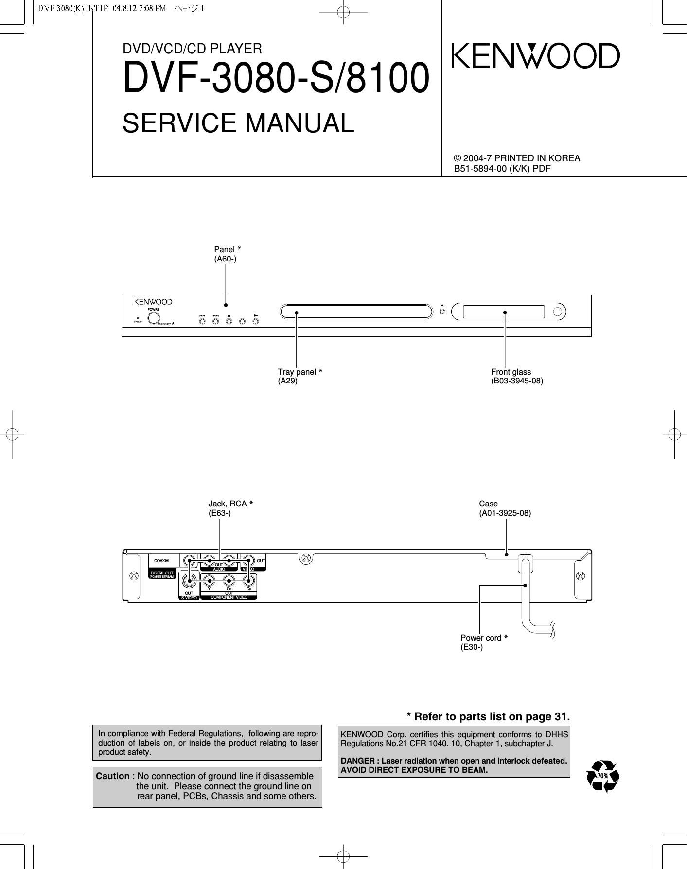
Panel *
(A60-)

KENWOOD l

rownz

l

\KJ/

m

L

Tray panel * Front glass
(A29) (803-3945-08)
/ \
K /
Jack, RCA * Case
(E63-) (A01 -3925-oa)

/ r
m lcojfewclpw @ I];
, , ¥ ®

glamour m fl 0

\\_// \\_l/
v in

Ca

(CIAFGHENTVlDEO

\L-fi
Power cord * /
(E30-)

* Refer to parts list on page 31.

In compliance with Federal Regulations, following are repro- KENWOOD Corp. certifies this equipment conforms to DHHS
duction of labels on, or inside the product relating to laser Regulations No.21 CFR 1040. 10, Chapter 1, subchapter J.
product safety.

DANGER : Laser radiation when open and interlock defeated.
AVOID DIFIECT EXPOSURE TO BEAM. .

Caution : No connection of ground line it disassemble
the unit. Please connect the ground line on
rear panel, PCBs, Chassis and some others_

Page 2

DVF73080(K)]NT1P 04.8.13 9:54 AM «3? Z

DVF-3080-S/81OO

CONTENTS / ACCESSORIES / CAUTIONS

CONTENTS

CONTENTS / ACCESSORIES / CAUTIONS ............... 2
DISASSEMBLY FOR REPAIR ..................................... 3
BLOCK DIAGRAM .................. 4

DECK MECHANISM... ...7

ELECTRICAL TROUBLESHOOTING GUIDE. .11
WAVEFORMS ............................................................ 15
ACCESSORIES

PC BOARD .............................
CIRCUIT VOLTAGE CHART ..
SCHEMATIC DIAGRAM
EXPLODED VIEW ......
PARTS LIST....
SPECIFICATIONS


Please confirm that the following accessories are present.

Audio cord (Red, White) ...(1)
(E30-7334-08) : K,P,Y
(E30-7335-08) : E,X

Video cable(Yellow) ...(1)
(E30-7332-08) :K.P.Y
(E30-7333-08) : E.X

Coaxial cable (Black) ...(1)
(E30-7336-08) : E.X
(E30-7337-08) : K.P.Y

Batteries (ROS/"AAA" -size) ...(2)

CAUTIONS

Operation to reset

unplugged while power is ON or due to an external factor.

The microprocessor may fall into malfunction (impossibility to operate erroneous display. etc.) when the power cord is

In this case, switch off the power, wait for several seconds, and then switch the power on again.

Note related to transportation and movement

Before transporting or moving this unit, carry out the
following operations.

1. Set the POWER ON/OFF switch to the ON
without loading a disc.

2. Wait a few seconds and verify that the display
shown appears.

"NO DISC"

3. Set the POWER ON/OFF switch to OFF.

Caution on condensation

Condensation (of dew) may occur inside the unit when there is a great
difference in temperature between this unit and the outside. This unit
may not function properly if condensation occurs. In this case, leave
the unit forafew hours and restartthe operation afterthe condensa-
tion has dried up.

Be specially cautious against condensation in the following circum-
stances:

When this unit is carried from one place to another across a large
difference in temperature, when the humidity in the room where
this unit is installed increases, etc.

The marking of products using lasers
(For countries other than U.S.A. and U.S.-Military)

CLASS 1

LASER PRODUCT

The marking this product has been classified as Class 1. It
means that there is no danger of hazardous radiation outside
the product.

Location: Back panel

Manufactured under license from Dolby Laboratories.
"Dolby" and the double-D symbol are trademarks of Dolby
Laboratories.

a

"DTS" and "DTS Digital Out" are reg-
istered trademarks of Digital Theater dit
Systems, Inc.

DIGITAL OUT

Page 27

6. SCART CIRCUIT DIAGRAM

DVF-3080-S/8I 00

Etc/Ami CpiioV A11 Stuffe She uses for Scar: Model Only ll!

FhAz
cF1osE1H1o1

T
1m
Fr'Drv Mam7CN601 7 T
CNBA 1 CFInaAaIlea
12v 1 7 5:; l L1
AU 111). H 9 $35? I «EA:
END 3 7 7 1 A. may
Ammo. L 4 7 2 A. 3LTN
_ g a A. ,an
0N3 a 4 6N3
a 5 5 END
UNJ 7 7 5 A. ,,I\l
_ 7 Enrico}
o 9 B VIDEOSTATUE
END 9 7 >7 9 GND
1: 10 55 _ 7 10 NC
, K 6.3;? 11 G ( 168]
15 = 9 1 A 7 a n
new, . 11 N. ./
SN) 12 Kncmam 7 $31433 13 GNU
VIDEO 13 >7 14 SN:
A / 4 7 15 mace}
are 15 HGESSTUE
F/C/D. SEL :5 ms 17 [SN]
,1271 1 16 7 + :nosemm >7 18 END
,1 17 E1 19 vouTicvus)
357? com arms. 7 20 VIVICVBS]
j? 73 1,3 7 470uF/S av 75 21 6N1
:: n5A1
A BAP 75 T
5 ms
Mrzfiééa K MTngfifi
, \ I ZDEAE /
K was: « ,v. W T}

CAUTION: For continued safety, replace safety critical com-
ponents only with manufacturer's recommended parts (refer
to parts list). A: indicates safety critical components. For
continued protection against risk of fire, replace only with

impedance type voltmeter with no

instruments used or on the product.

same type and rating fuse(s). To reduce the risk of electric
shock, leakage-current or resistance measurements shall be
carried out (exposed parts are acceptably insulated from the
supply circuit) before the appliance is returned to the cus-

tomer.

The DC voltage is an actual reading measured with a high

signal input. The mea-

surement value may vary depending on the measuring

29