Kenwood DVF 3080 Service Manual

This is the 34 pages manual for Kenwood DVF 3080 Service Manual.
Read or download the pdf for free. If you want to contribute, please mail your pdfs to info@audioservicemanuals.com.

Page: 1 / 34
left right
Kenwood DVF 3080 Service Manual

Extracted text from Kenwood DVF 3080 Service Manual (Ocr-read)


Page 1

DVF73080(K)]NT1P 04.4.12 9:53 AM \°-A/1

DVD/VCD/CD PLAYER

DVF-3080-S/8100

SERVICE MANUAL

TENTATIVE

© 2004-4 PRINTED IN KOREA
B51-5894-00 (K/K) 1360

KENWOOD

I L

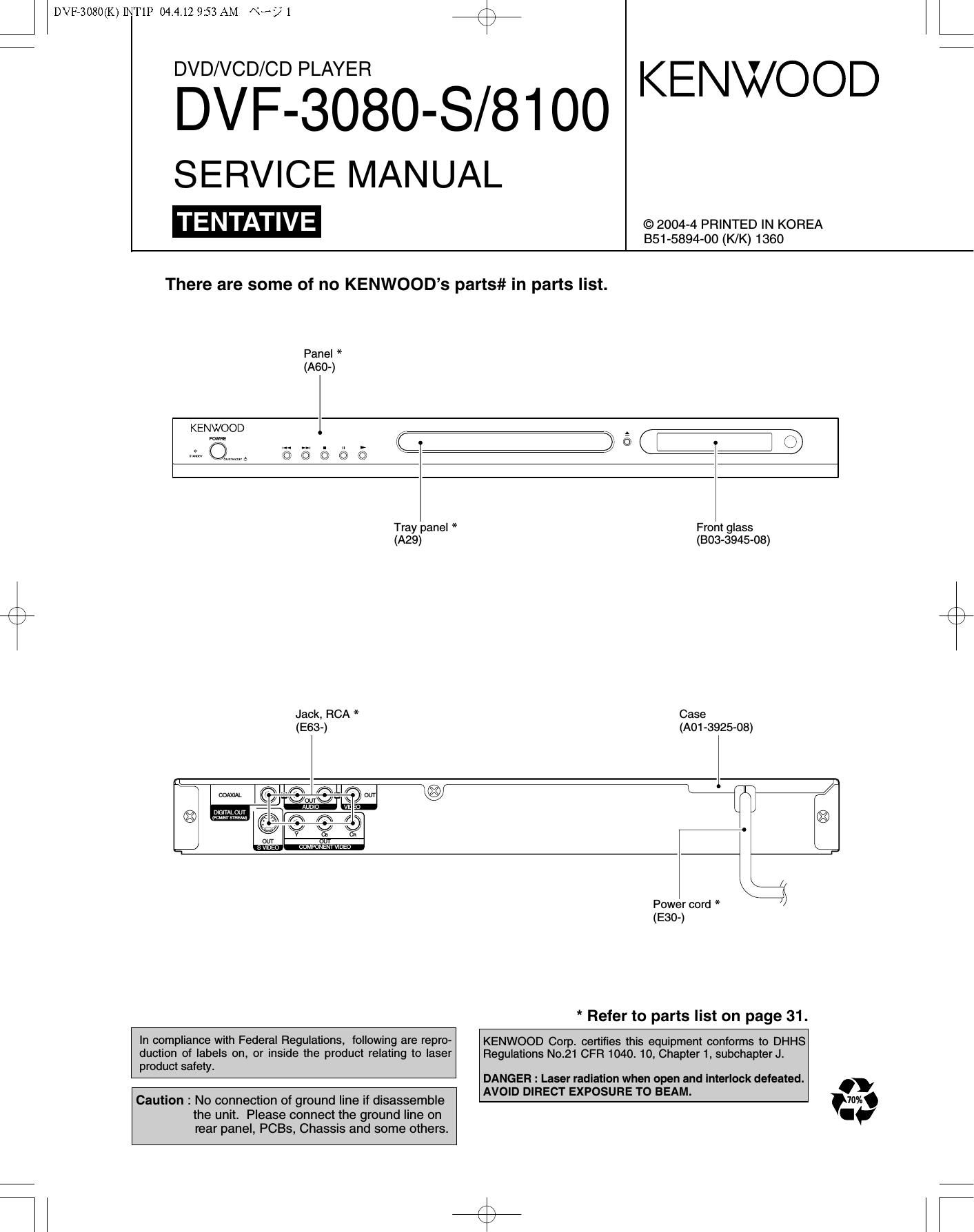
There are some of no KENWOODs parts# in parts list.

Panel *
(A60-)

KENWOOD I,

Fawn:

\KJ/

m

Tray panel * Front glass
(A29) (303-3945-08)
Jack, RCA * Case
(E63-) (AO1-3925-08)
l l /
mm lim flLI Kr? W 23 gfl-/
u

divwvr§

x gems? _, ; ,
O @e e 0 ®
v u an
M COMPONENIVIDED
\j
Power cord * /
(E30-)
* Refer to parts list on page 31.
In compliance with Federal Regulations, following are repro- KENWOOD Corp. certifies this equipment conforms to DHHS
duction of labels on, or inside the product relating to laser Regulations N021 CFR 1040. 10, Chapter 1, subchapter J.
product safety
DANGEFI : Laser radiation when open and interlock defeated.
. . . . . AVOID DIFIECT EXPOSURE TO BEAM. .
Caution : No connection of ground line If disassemble m.

the unit. Please connect the ground line on
rear panel, PCBs, Chassis and some others

Page 2

DVF73080(K)]NT1P 04.4.12 9:53 AM «3? Z

DVF-3080-S/81OO

ACCESSORIES / CAUTIONS

Accessories

Please confirm that the following accessories are present.
Video cable(Yellow) ...(1)

Audio cord (Red. White) ...(1)

Remote control unit ...(1)
(A70-1660-08)

(o

Coaxial cable (Black) ...(1)

...(2)

Cautions

Operation to reset

The microprocessor may fall into malfunction (impossibility to operate erroneous display, etc.) when the power cord is
unplugged while power is ON or due to an external factor.
In this case, switch off the power, wait for several seconds, and then switch the power on again.

Note related to transportation and movement
Before transporting or moving this unit, carry out the
following operations.

1. Set the POWER ONIOFF switch to the ON
without loading a disc.

2. Wait a few seconds and verify that the display
shown appears.

"NO DISC"

3. Set the POWER ONIOFF switch to OFF.

Caution on condensation

Condensation (of dew) may occur inside the unit when there is a great
difference in temperature between this unit and the outside. This unit
may not function properly if condensation occurs. In this case, leave
the unit for a few hours and restart the operation after the condensa-
tion has dried up.

Be specially cautious against condensation in the following circum-
stances:

When this unit is carried from one place to another across a large
difference in temperature, when the humidity in the room where
this unit is installed increases, etc.

The marking of products using lasers
(For countries other than U.S.A. and U.S.-Militaly)

CLASS 1

LASER PRODUCT

The marking this product has been classified as Class 1. It
means that there is no danger of hazardous radiation outside
the product.

Location: Back panel

Manufactured under license from Dolby Laboratories.
"Dolby" and the double-D symbol are trademarks of Dolby
Laboratories.

"DTS" and "DTS Digital Out" are reg- "
istered trademarks of Digital Theater dlt
Systems, Inc.

DIGITAL OUT

Page 10

DVF73080(K)]NT1P 04.4.12 9:53 AM «3? 10 / \

DVF-3080-S/81OO

DECK MECHANISM DISASSEMBLY

GEAR LOADING

GEAR PULLEY

BASE MAIN

GUIDE UP/DOWN

FIG. (o)

GUIDE UP/DOWN

GUIDE UP/DOWN

Fig. 4-4

5. Frame Assembly Up/Down (Fig. 4-4)
Note

Put the Base Main face down(Bottom Side)

1) Release the screw(S4)

2) Unlock the Locking Tab(LS) in direction of arrow and
then lift up the Frame Assembly Up/Down to separate
it from the Base Main.

Note

- When reassembling move the Guide Up/Down in direction
of arrow(C) until it is positioned as Fig.(C).

- When reassembling insert (A) portion of the Frame
Assembly Up/Down in the (B) portion of the Guide
Up/Down as Fig.(B)

6. Belt Loading(Fig. 4-4)

Note

Put the Base Main on original position(Top Side)

7. Gear pulley (Fig. 4-4)

1) Unlock the Locking Tab(L4) in direction of arrow(B) and
then separate the Gear Pulley from the Base Main.

8. Gear Loading (Fig. 4-4)
9. Guide Up/Down (Fig. 4-4)
1) Move the Guide Up/Down in direction of arrow(A) as
Fig-(A)
2) Push the Looking Tab(L5) down and then lift up the
Guide Up/Down to separate it from the Base Main.
Note
When reassembling place the Guide Up/Down as Fig.(C)
and move it in direction arrow(B) until it is locked by the
Locking Tab(L5). And confirm the Guide Up/Down as Fig.(A)
10. PWB Assembly Loading (Fig. 4-4)
Note
Put the Base Main face down(Bottom Side)
1) Release 1 Screws(85)
2) Unlock the Loading Motor (02) from the Hook (H1) on
the Base Main.
3) Unlock 2 Locking Tabs(L6) and separate the PWB
Assembly Loading from the Base Main.

11. Base Main(Fig. 4-4)

Page 11

Ll

1. Power check flow

A.

Is there a DC voltage At
(+) terminal ol 50101?

B.
NO VF+ NO 5V7A
NO NO
ls 5.2VA section working? ls 5.2VA section working?
YES i YES i
Check F102 No 5 ZVA No Is 5.2V present at emitter
' of 0107?
YES i i YES i
Replace D102. Check F101 Replace 0107.
i YES i
Is there a DC Voltage at NO
R101? Replace R101.
NOi YES i
No

Replace BDIOI.

YEsi

Replace ICIOI.

note: This Trobleshooting has various information.

2. System operation flow

Power on

1.initializes SERVO, DSP and RISC registers
2.wrtte RISC code to SDRAM
3.Reset RISC

Show LOGO
SLED at Inner Side?

no

SLED Moves to Inner Position

->
Tray Closed?
no
Tray Close to closed position
<-
1.Judge whether have disc and disc type
2.Jump to related disc reading procedure

yes


Received
0 en/close ke 7

no
1.Execute Pressed Key and IR Key
2.System operation on routine loop
1.Slop playback and open tray
2.Display tray open message and LOGO
->

no Receive
close key?


30in!) 9NLLOOHSE'IflnOHl 'IVOIHLOEI'IEI

00 LB/S'OBOS'jAG

N WV £936 III/{70 dilNI (XIOSOSHAG

Hf: