Kenwood DV 6050 Service Manual

This is the 46 pages manual for Kenwood DV 6050 Service Manual.
Read or download the pdf for free. If you want to contribute, please mail your pdfs to info@audioservicemanuals.com.

Page: 1 / 46
left right
Kenwood DV 6050 Service Manual

Extracted text from Kenwood DV 6050 Service Manual (Ocr-read)


Page 1

DV6050(K)INT1P 02.10.175:59 PM \°-/1 /\
\J

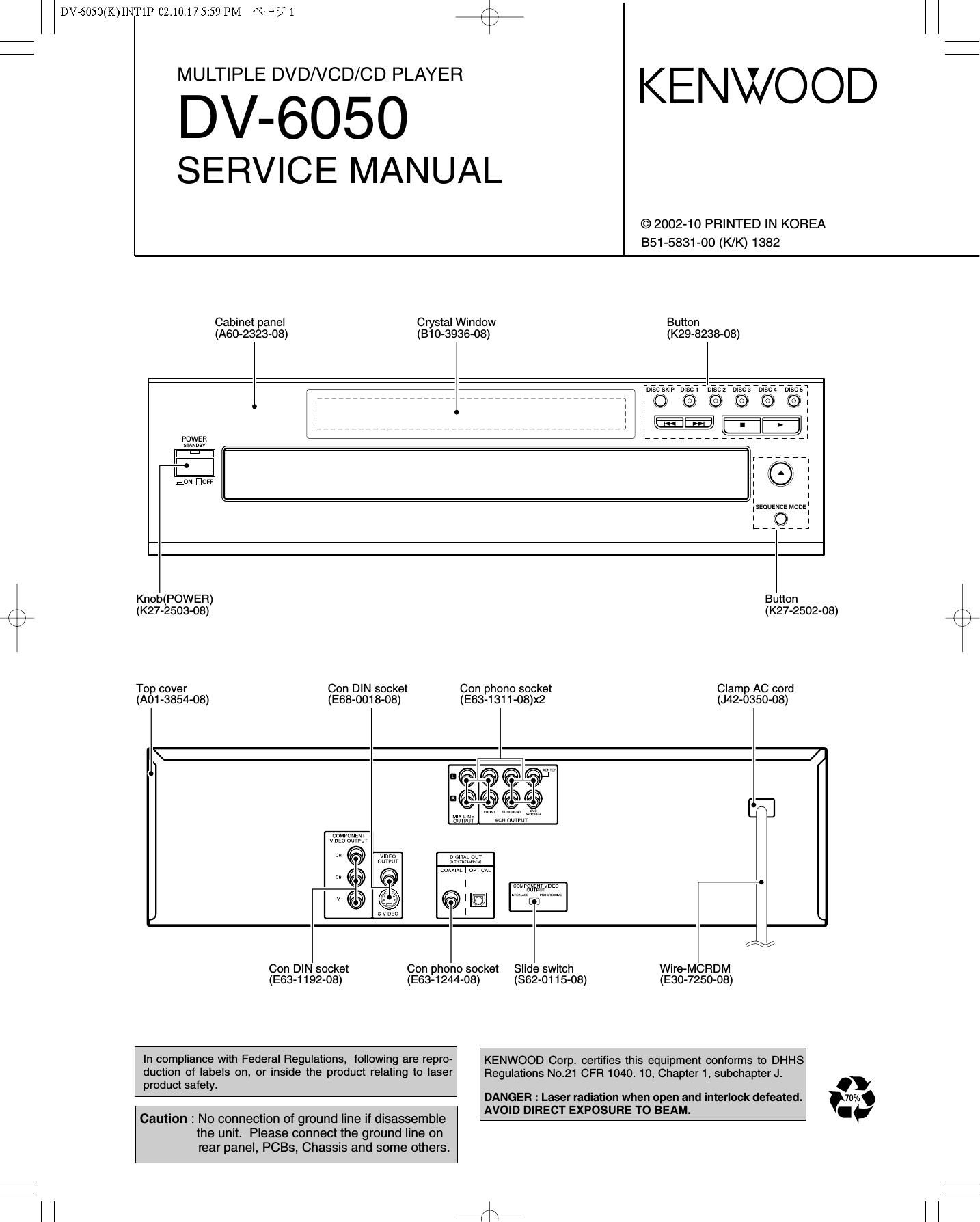
7 MULTIPLE DVD/VCD/CD PLAYER KE NWO O D
DV-605O

SERVICE MANUAL

© 2002-10 PRINTED IN KOREA
851-5831-00 (K/K) 1382

Cabinet panel Crystal Window Button
(A60-2323-O8) (B10-3936-08) (Kze-azas-os)
ragga: EEC: .2352 3.3;; 97ng wisps]
; 7777777777777777777777777777777777777777777 z ; o o o o o k, .
l
Elli?
E
I-
noNfloFr
Knob(POWER) Button
/ \ (K27-2503-08) (K27-2502-08) / x
k / \
Top cover Con DIN socket Con phono socket Clamp AC cord
(A01 -3854-08) (E68-0018-08) (E63-1311-08)x2 (J42-0350-08)

Beggiglg

w LINE mm
mm


am Wm

cot/PoNEN
vlnzo ourvu

0 vmzo mam OJ
ourwur I." saw

mm | mum

v© TI o;-
Con DIN socket Con phono socket Slide switch Wire-MCRDM
(E63-1 192-08) (E63-1244-08) (862-01 15-08) (E30-7250-08)

In compliance with Federal Regulations, following are reprO- KENWOOD Corp. certifies this equipment conforms to DHHS

duction of labels on, or inside the product relating to laser Regulations No.21 CFR 1040 10, Chapter 1, subchapter J.

product safety .
DANGER : Laser radiation when open and interlock defeated. WA
AVOID DIRECT EXPOSURE TO BEAM. I.

Caution : No connection of ground line if disassemble
the unit. Please connect the ground line on
rear panel, PCBs, Chassis and some others.

Page 2

r\
\/

DV6050(K)INT1P 02.10.17 5:59 PM «392

DV-605O

/\
\/

CONTENTS / ACCESSORIES

Contents

CONTENTS / ACCESSORIES .....
DISASSEMBLY FOR REPAIR ......
CIRCUIT DESCRIPTION.
ADJUSTMENT .................
INTERCONNECTION DIAGRAM .

PC BOARD .............................................................. 21

Accessories

SCHEMATIC DIAGRAM .. ..... 28
EXPLODED VIEW ................. 43
PARTS LIST ................................. 44
SPECIFICATIONS ..... Back cover

Please confirm that the following accessories are present.

Audio video cord (Red, White, Yellow) ...(1)
(E30-2990-08)

Remote control unit ...(1)
(A70-1631-08)

BatteriesIROB/AA) ...(2)

Coaxial cable ...(1)
(E30-7235-08)

The marking of products using lasers
(For countries other than USA, US.-
Military and Canada)

CLASS 1

LASER PRODUCT

The marking this product has been classified as Class
1. It means that there is no danger of hazardous
radiation outside the product.

Location: Back panel

CAUTION

VISIBLE LASER RADIATION
WHEN OPEN. DO NOT

Inside this laser product, a laser diode classified as
Class 2 laser radiation is contained as alerted by the
internal caution label shown above. Do not stare into
beam.

Location: DVD laser pick-up unit cover inside this
product

Page 4

DV6050(K)INT1P 02.10.175:59 PM \°-/4

DV-6050

DISASSEMBLY FOR REPAIR

4. Pull out the DVD mechanism horizontally.
5. Up-side-down the DVD mechanism.

[I ©7777,». LEI:
l 777777777777777 is
@,.,,,,j @ BOTTOMVlEW
. f M H
a L:
I;
Fig.3

6. Remove screws (®x4) and DVD ED.
7. Unplug the connectors ( CN15,CN53,CN55,CN74) and
disconnect 3 flexible cables (CN1,CN2,CN33).

CN53 \ , .
% CN2 \
\ o / CN1

rx
\/

Paw
CN55

8. For the assembly procedure, follow the item 5 to 3 in
reverse.
9. Set up the DVD B'D on the top as figure 5.

10. Connect a jig (E35-2113-05) to CN33 instead of an origi-
nal flexible cable (E35-1990-05).

9N33 Parts No. Remark
(FleXIble cable)
Original E35-1990-05 22cm
1
* JIG E35-2113-05 35cm

* (This is a jig for video signal adjustment, after adjusted
it put back to an original flexible cable.)
11. Plug in the connectors (CN15,CN53) and connect 2 flexi-
ble cables (CN1,CN2).
* Note : The connectors (CN55, CN74) are for audio sig-
nal line so that no necessary to put it back when
video signal output adjustment.

Use an lnstalting Material

Fig. 5

12. Follow the item 2 and 1 in reverse.
13. Gruond DVD ED and rear panel as figure 5.
14. Follow the video signal output adjustment procedure.

Page 17

r\
\J

DV6050(K)INT1P 02.10.17 6:00 PM «3? 17

/\
\/

DV-6050

CIRCUIT DESCRIPTION

Pin No. Pin Name l/O Pin Description
5:233:3227 HDO~HD15 l/O DVD microcomputer data bus 0~15.
69 AUDSTR | Valid signal of bit stream input data.
70 VSTR | Clock signal input for bit stream.
71 VRQ 0 Request of program stream.
73~76,78~81 STD7~STDO | Bit stream parallel input 0~7.
83 IECOUT O |EC958 format data output.
84 DMIX 0 Down mix signal output (CH7/CH8).
86 DACCK 0 Over sampling DAC clock output.
87 LRCK 0 LR clock output.
88 SRCK 0 Bit clock output.
90~92 ADOUT(0~2) 0 Audio data output (0~2).
94 CLK121 | External clock (121.5MHz) input. (Unused)
95 CKlO | "L" : Fixed
96 CLK27 | System clock input (27MHZ).
97 PLLVDD Supply voltage (+1.8V) of internal logic for main PLL.
98 CLK81 - Connected to digital ground.
100 EXTCK | Clock input for audio.
101 PLLAVDD - Main PLL supply voltage (+3.3V).
102 TCPOUT 0 Unused.
103 PLLAVSS - Ground for main PLL.
106 PHCOPMO 0 Audio PLL phase comparison output.
107 APLLVDD - Supply voltage (+1.8V) of internal logic for Audio PLL.
108 ACKIO | "L" : Fixed
109 MODE121 | Switching port for SDRAM clock frequency.
110 DCTEST | DC test mode terminal.
111 APLLAVSS Ground for audio PLL.
112 APLLAVDD - Supply voltage (+3.3V) for Audio PLL.
113 VREFCR | DAC reference voltage input for CR signal.
114 IREFCR | DAC bias current setting port for CR signal.
115 COMPCR | Capacitance connection for DAC (CR signal) stabilization.
116 VCROUT 0 CR signal output for DAC.
117,127 AVDD - Analog supply voltage (+3.3V) for DAC.
118 VREFC | DAC reference voltage input for C signal.
119 IREFC | DAC bias current setting port for C signal.
120 COMPC | Capacitance connection for DAC stabilization.
121 VCOUT O C signal output for DAC.
122,132 AVSS - Analog ground for DAC.
123 VREFCB | DAC reference voltage input for CB signal.
124 IREFCB | DAC bias current setting port for CB signal.
125 COMPCB | Capacitance connection for DAC (CB signal) stabilization.
126 VCBOUT 0 CB signal output for DAC.
128 VREFY | DAC reference voltage input for Y signal.
129 IREFY | DAC bias current setting port for Y signal.
130 COMPY | Capacitance connection for DAC (Y signal) stabilization.
131 VYOUT O Y signal output for DAC.
133,134 TESTSEL1,0 | Test mode terminal. L : Fixed
136 VCLK O Clock output for digital video data output.
137~140,142,143 REC(7~2) l/O RE0656 input (7~2).
144 XVFSIE((l3\lI(30 I/O REC656 input 1. Vertical synchronizing signal input/output.
145 RECO l/O REC656 input 0. Horizontal synchronizing signal input/output.
XHSYNCO
147~150,152~155 VDO~VD7 0 Digital video data output (0~7).

17