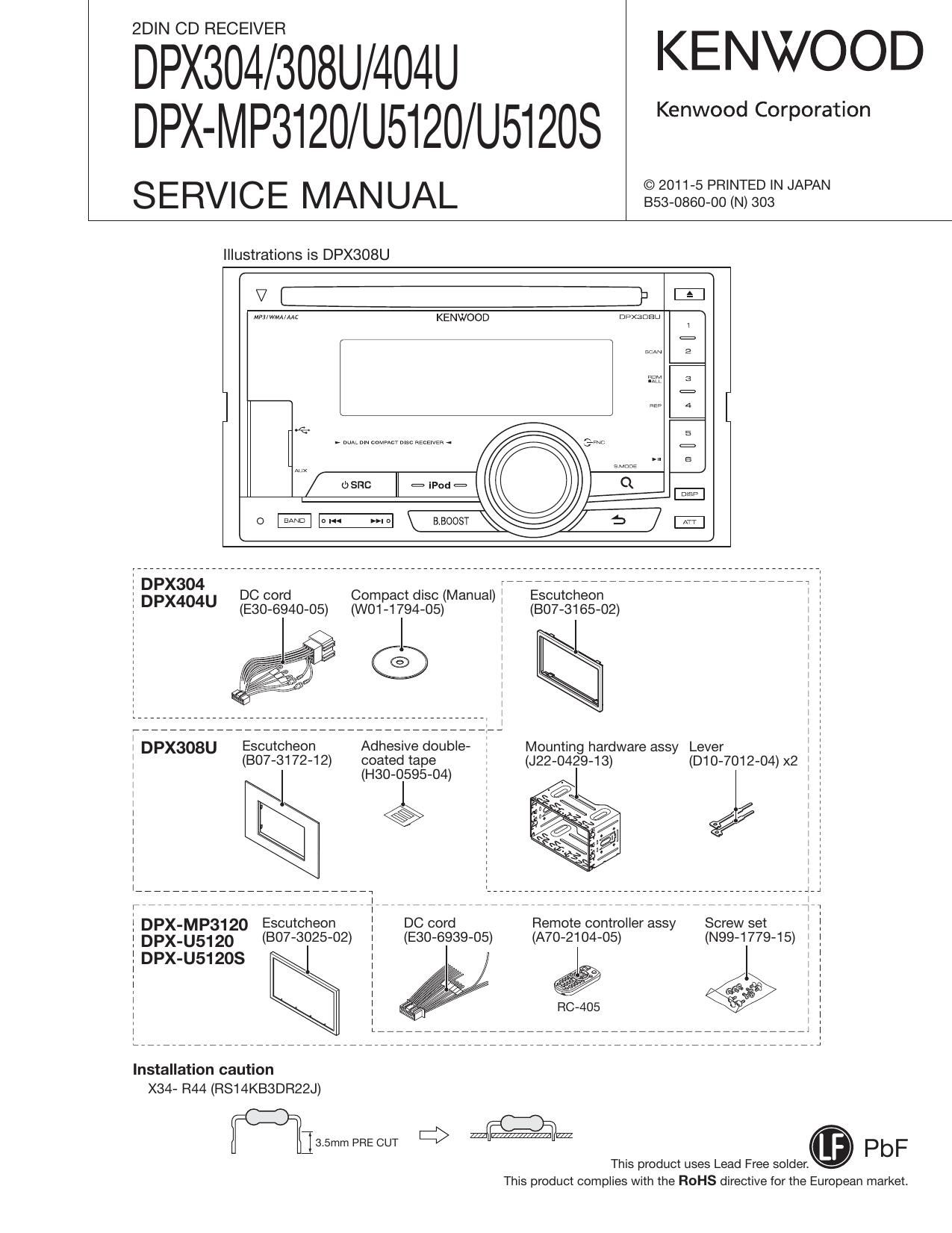
Kenwood DPXMP 3120 Service Manual

This is the 58 pages manual for Kenwood DPXMP 3120 Service Manual.
Read or download the pdf for free. If you want to contribute, please mail your pdfs to info@audioservicemanuals.com.

Page: 1 / 58
left right
Kenwood DPXMP 3120 Service Manual

Extracted text from Kenwood DPXMP 3120 Service Manual (Ocr-read)


Page 11

DPX304/DPX308U/DPX404U
DPX-MP3120/U5120/U51208
TEST MODE

0 Description explanation
Display specification of this document is described by the following forms.

EE E EE E+E E E+E E+E+E

Key Description of display Description

5 D E E .ID D Disc Eject count display (Max. 65535 times).

Disc Eject

l5 unmismay E E E [E E E E E E E

*A symbol I" in the key column indicates that the key should be pressed and held.

While Disc Eject count is displayed, press and hold for 2
seconds or longer to clear Disc Eject count.

2. Test mode function
0 How to transfer to the mode
Perform the reset operation while pressing and holding [B.BOOSTJ + [SEARCH] to transfer to the test mode.

V

m WM KENWQQD UquEDD

0 How to clear the mode

Clear the test mode with the conditions below.
0 Reset

0 Momentary power down detection

0 ACC OFF operation

0 POWER OFF operation

0 Limitation/ special remarks in the mode

0 When detecting the disconnection of the oscillator for sub-clock, all lights ON display flashes.

0 When the unit starts with the test mode, change the LINE MUTE inhibit time from 10 seconds to 1 second.

0 In the test mode, do not write serial with the serial write jig.

0 In the test mode, the DC error detection information is not written in Data Flash even if the DC error detection is performed.

0 DEMO mode shall not operate in the test mode. Also, when the source is STANDBY, do not display DEMO ON/OFF switching
items in the FUNCTION.

0 DISC forced load operation prohibited in the test mode.

11

Page 17

DPX304/DPX308U/DPX404U
DPX-MP3120/U5120/U51208

TEST MODE

(2) TUNER setting adjustment mode (MANUAL)

Key Description of display Description
[Level Offset adjustment (Manual)j
S-xx: Current S-meter value (Hex)
Normal display E D B D E L-xx: Level offset value (Hex)
*When the level offset value is not adjusted (OxFF or
0x00), - is displayed.
Level Offset
l«/»l _ Press [l«]/[»l] key for 500ms or longer to continuously
ad ustment S L
I l«/»l J E D B D E increase/ decrease the adjustment value
(Manual)
Com letion of
the ag'ustment Level offset value Displayed when an adjustment value(s) was written to
value] savin E D E D D D D D: the data flash. The level offset value (Hex) is displayed.
ENTER F _| d t g
ai e 0 save
. Displayed when adjustment value(s) was not written to
the adlustment E D D D D D D D D the data flash
value
DISP Adjustment mode Press the key briefly to enter the TUNER setting ad-
switching justment mode (AUTO).
A'l'l' Adjustment mode Press the key briefly to enter the TUNER setting ad-
switching justment mode (AUTO).
RETURN Mode clear Clear the adjustment mode to transfer to the TUNER
special display mode.

<> S-meter voltage evaluation mode
This mode is to display the S-meter present voltage (Hex) and to check and evaluate if the voltage is within the criteria or not (OK

or NG).
Check and evaluate the voltage only after the completion of the TUNER setting adjustment. (When the setting is not yet ad»
justed4 -" is displayed.)

When receiving AM, do not select this mode.
When this mode, the BAND switching and SEEK operations such as operation of [BAND], [I44]/[»l], and [PRESET] keys shall be
prohibited.
Key Description of display Description
[S-meter value]
XX: Current S-meter value (Hex)
[S-meter value evaluation result]
3mm, Evaluauon OK: S-meter voltage is within the range of the criteria
SSU (J type: 0xA5~0xAF)
(Other than J type: 0xA3-0xAD)
NG: S-meter voltage is outside the range of the crite-
ria (Other than defined above)
- -: TUNER setting is not yet adjusted
Clear the adjustment mode to transfer to the TUNER
special display mode.

S-meter voltage
evaluation display


RETURN Mode clear

17

Page 22

DPX304/DPX308U/DPX404U
DPX-MP3120/U5120/U51208

TEST MODE

7. ROM correction writing-in function
0 How to transfer to the mode

While pressing and holding [PRESET-G] + [SEARCH], reset to transfer to the ROM correction writing-in mode.

The opening display shall be omitted for the easy recognition of the mode transfer

in this mode, DOP setting is unavailable (Except only for DOP TYPE display).

In the old model, after the mode transfer, the operation is possible to become unstable due to the ununiformity of the respec-

tive keys effectiveness.

And considering the confusion due to an accidental press in the line, the keys other than [EJECT] key shall be disabled.

V

L) sac

KENWOOD

ll =.p..= (

aaoosr

After entering to this mode, insert DISC and USB.

The display of the SRC switching is shown in the same manner as the display of the normal mode.
After the completion of Reading, start the Update if there is an update file.

If there is no update file, display NO FILE".

Note that the DEMO mode display in ROM correction UPDATE mode will cause the Delay of the mask or the beginning of start-

up.

*According to the internal software specification, DEMO mode ON setting shall be disabled. And during the ROM correction
UPDATE, it shall keep initializing the timer for DEMO mode startup management.

Key Description of display

Description

IIIIEEEEEEE

STANDBY condition in the forced ROM correction data update mode

EEIEE EEEEEE

Display of READING in progress. a Display in 2H2 blinking

IIIIEEEEEEEEE

The NO FILE" is displayed when there is no update file

IIIIEEEEEEEEE

Display after confirming the existence of an update file, Display in Up-
dater « Display in 2H2 blinking

IEEEEE-EEEEEEE

Completion of the UPDATE (the number in 3 digits displays the version)

*This version is the FM Update versiont

:1 For the ROM correction versions of respective p-coms (System p-com/
Panel/ Bolero), refer to the FM management table.

IEEEEEEEEEEEE

Failure of the UPDATE

22

Page 55

DPX304/DPX308U/DPX404U
DPX-MP3120/U5120/U51208

PARTS LIST

CD MECHANISM ASSY (X92-6320-00) (DXM-QB10W)
CD MECHANISM ASSY (X92-6360-04) (DXM-9334W)

A N . . Desti- A N . . Desti-
Ref. No. 3 vev Parts No. Descrlphon nation Ref. No. 3 vi Parts No. Description nation
16 2A D104995-03 SLIDER DM1 28 X94-2090-00 SPINDLE MOTOR ASSY
17 28 D10A4996»02 SLlDER DM2 28 X94-2100-00 FEED MOTOR ASSY (LOAD/SLED)
18 2A D10'4997-03 LEVER DPU1 28 X93-2280-00 OPTICAL PICKUP ASSY
19 1A D10-4998-03 ARM
20 2A D104999-03 ARM
21 2A D10-7001-03 ARM
22 2A D10-7002-03 ARM
23 2A D10-7003-03 ARM
24 2A D13-2445»04 GEAR
25 2A D13-2446-04 GEAR
27 2A D13-2448-04 GEAR
28 2A D13-2449-04 GEAR
29 2A D13A2450»04 GEAR
30 2A D13A2451-04 GEAR
31 2A D13-2452-04 GEAR
32 2A D13-2453»04 GEAR
33 2A D13-2454-04 GEAR
34 2A D13-2455-04 GEAR
35 28 D13-2456-03 RACK (GEAR)
36 2A D14-1028»04 ROLLER
37 3A D21-2507-04 SHAFT
38 28 D21-2508-04 SHAFT
39 3A D23-0963-04 RETAINER
4O 38 D39-O277-15 DAMPER
41 38 D39AO278-15 DAMPER
46 18 G01-4682-34 TORSION COIL SPRING
47 3A G01-4756-04 EXTENSION SPRING
48 2A G01-4684-04 EXTENSION SPRING
49 28 G01-4685-04 EXTENSION SPRING
50 18 G01-4686»14 EXTENSION SPRING
51 3A G01-4688-14 EXTENSION SPRING
52 3A G01~4692-24 TORSION COIL SPRING
54 3A G02-1588-04 FLAT SPRING
55 18 G13-1297-04 CUSHION (CLAMPER CUSSIO
56 1B G13-1299-14 CUSHION (STROKE CUSHION
57 1A G16~1715-04 SHEET
61 18 J11-0675-03 CLAMPER
64 2A J19-7210-21 HOLDER
65 28 J19-7225-04 HOLDER
66 1B J22»0706~03 MOUNTING HARDWARE
67 1A J22-0707-12 MOUNTING HARDWARE
68 18 J90-1166A11 GUIDE
69 28 J90»1168-03 RAIL
A 1A NOB-610615 TAPTITE SCREW (M2X315)
B 28 NOB-642615 MACHINE SCREW (LOAD ARM SCREW
C 28 NOB-673505 TAPTITE SCREW (PICK SCREW)
D 28 NOB-67374 5 MACHINE SCREW (SHAFT SCREW)
E 28 NOB-673615 TAPTITE SCREW (GEAR SCREW)
F 2A N19-2335»14 FLAT WASHER
G 28 NBS-200348 B1ND|NG HEAD MACHINE SCREW
H 28 N39-1720-4B PAN HEAD MACHINE SCREW
76 2A S68~OB21~05 PUSH SWITCH
E2: DP><404U E3: DPX304 (Europe) K1: DPX308U (North America) Alndicates safety critical components.

M12DPX-U5120 M2: DPX-U512OS M3: DPX-MP3120 (OtherAreas)
55