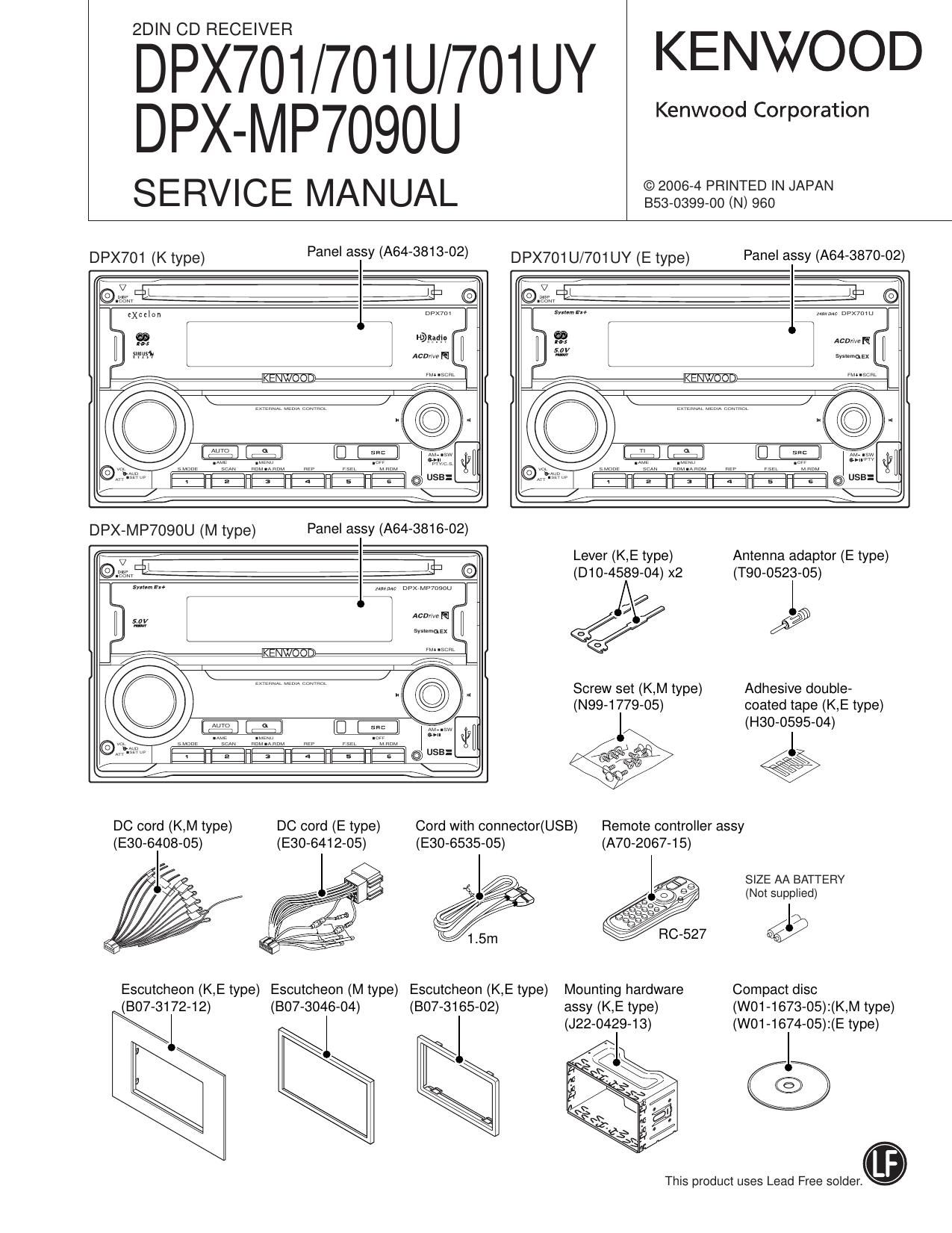
Kenwood DPX 701 U Service Manual

This is the 56 pages manual for Kenwood DPX 701 U Service Manual.
Read or download the pdf for free. If you want to contribute, please mail your pdfs to info@audioservicemanuals.com.

Page: 1 / 56
left right
Kenwood DPX 701 U Service Manual

Extracted text from Kenwood DPX 701 U Service Manual (Ocr-read)


Page 14

DPX701/701U/701UY
DPX-MP7090U

MICROCOMPUTERS TERMINAL DESCRIPTION

14

O MECHANISM MICROCOMPUTER: M30620FCPGP (X32: IC1)

Pin No. Pin Name l/O Application Processing Operation Description
1~5 NC - Not used Opened output L fixed
6 BYTE l External data bus SW input Connects to GND
L: Single chip mode
7 CNVSS l Processor mode SW
H: Microprocessor mode or flash ROM writing
8 m 0 Audio mute control L: Mute ON, H: Mute OFF
9 NC - Not used Opened output L fixed
10 FSET I Reset detection L: Reset (Flash ROM writing), H: Normal
11 XOUT 0 Main clock output Connects to resonator
12 VSS - Power supply input Connects to GND
13 XIN l Main clock input Connects to resonator
14 VCC1 - Power supply input Connects to BU3.3V
15 W l NMI interruption input Input Hi (Pull-up) fixed
16 MSTOP l STANDBY comeback interrupption L: Stop, H: Stop cancelled (Hi edge)
17 NC - Not used Opened output L fixed
18 DSP INT l DSP interruption signal input H: Interruption (Hi edge)
19~22 NC - Not used Opened output L fixed
Series resistors and E2PROM are not built when
23 E2P SCL |/O E2P |2C clock output
ROM collection is not used.
Series resistors and E2PROM are not built when
24 E2P SDA l/O E2P IZC data input and output
ROM collection is not used.
25,26 NC - Not used Opened output L fixed
27 SCL | System p-com IZC clock input
28 SDA l/O System p-com IZC data input and output
29 DSP TXD 0 Data output for DSP serial data Flash ROM writing: TXD (Pull-up)
3O DSP RXD I Data input tor DSP serial data Flash ROM writing: RXD
31 DSP CLK O Clock output for DSP serial data Flash ROM writing: SCLK(Pull-up)
32 DSP STB (BUSY) O DSP data strove signal output Flash ROM writing: BUSY
33 CS SDATA 0 Data output for decoder serial data
34 CS BDATA I Data input tor decoder serial data
35 CS CLK O Clock output for decoder serial data
36~38 NC - Not used Opened output L fixed
39 fill - Not used (Flash ROM: EPM) Opened output L fixed
40 PON D33 0 D3.3V POWER ON control H: POWER ON, L: POWER OFF
41 PON A5 0 A5.0V POWER ON control H: POWER ON, L: POWER OFF
42 PON 081 O |C15 series 3.3V POWER ON control H: POWER ON, L: POWER OFF
43 PON C82 0 |C15 series 1.8V POWER ON control H: POWER ON, L: POWER OFF
44 GTE - Not used (Flash ROM: CE) Opened output L fixed
45 m 0 Driver mute L: Stop, H: Mute OFF
46,47 NC - Not used Opened output L fixed