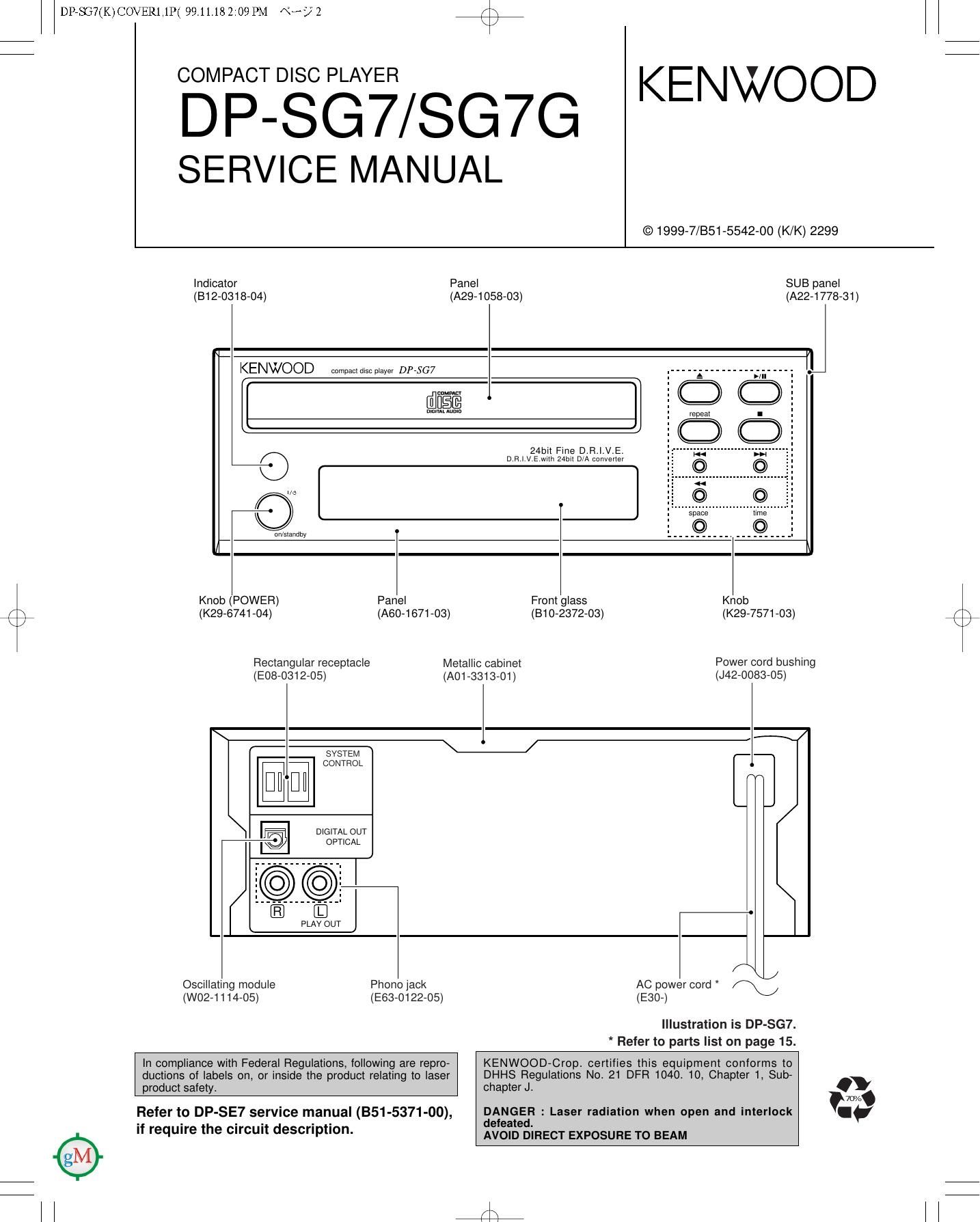
Kenwood DPSG 7 Service Manual

This is the 14 pages manual for Kenwood DPSG 7 Service Manual.
Read or download the pdf for free. If you want to contribute, please mail your pdfs to info@audioservicemanuals.com.

Page: 1 / 14
left right
Kenwood DPSG 7 Service Manual

Extracted text from Kenwood DPSG 7 Service Manual (Ocr-read)


Page 1

DPeSG7(K)COVER1,1P( 99 11.18 2:09 PM \°~:/°Z /\
\/

3310§E§YE7VSG7G KENWOOD

SERVICE MANUAL

© 1999-7/851-5542-00 (K/K) 2299

Indicator Panel SUB panel
(B12-0318-04) (A29-1058-03) (A22-1 778-31)

KENWOOD compacldiscplayev 0.07507

i am i

t J

24bit Fine D.R |.V.E,

O D R I v E mm 2mm DlA convevfer

Uri/standby

Knob (POWER) Panel Front glass Knob
C) (K29-6741-04) (A60-1671-03) (810-2372-03) (K29-7571-03)
Rectangular receptacle Metallic cabinet POWGV cord bushing
(E08-0312-05) (AO1-3313-O1) (J42-0083-05)
l d


SYSTEM

I DIGITAL OUT
-° lb]; OPTICAL


/ ./
Oscillating module Phonojack AC power cord /\/

(W02-1114-05) (12153-012205) (1230-)

Illustration is DP-SG7.
* Refer to parts list on page 15.

In compliance with Federal Regulations, following are repro- KENWOOD-Cropt certifies this equipment conforms to
ductions of labels on, or inside the product relating to laser DHHS Regulations No. 21 DFR 1040. 10, Chapter 1, Sub-
product safety chapter Jt .
707::
Refer to DP-SE7 service manual (BS1 -5371 -00), DANGER : Laser radiation when open and interlock I'
- - - - - - defeated.
If reqUIre the Circufl description. AVOID DIRECT EXPOSURE To BEAM

l l 4

Page 2

DPeSG7(K)COVER1,1P( 99.11.18 2:09PM \°-/ 3 /\

DP-SG7/SG7G

CONTENTS / CAUTIONS

Contents
CONTENTS / CAUTIONS ............. SCHEMATIC DIAGRAM .....
DISASSEMBLY FOR REPAIR EXPLODED VIEW
ADJUSTMENT PARTS LIST....
PC BOARD ........ SPECIFICATIONS
Cautions
Mariam
C) Themicrocomputer mayfall into malfunction (impos-
sibility to operate, erroneous display, etc.) when the DPSG7
power cord is unplugged while power is ON or due Pull 1"? WW? PIUQ from the receptacle, and then
to an attemal factor. In this case, aecutethefollow- PIUQ 5 "1 agam.

ing procedure to rset the microcomputer and retum
it to normal condition.

0 Please note that resetting the microcomputer clears
the contents stored in it returns it to condition when it
left the factory.

Page 3

DP75G7(K)COVER1,1P( 9911.18 2:09PM \°-/ 6 <\

DISASSEMBLY FOR REPAIR

How to open tray if not comes out.

1. Insert screwdriver to hole on bottom plate and turn screw
clockwisely about 100° (0).

2. Pull tray out by hand if tray comes out (9).