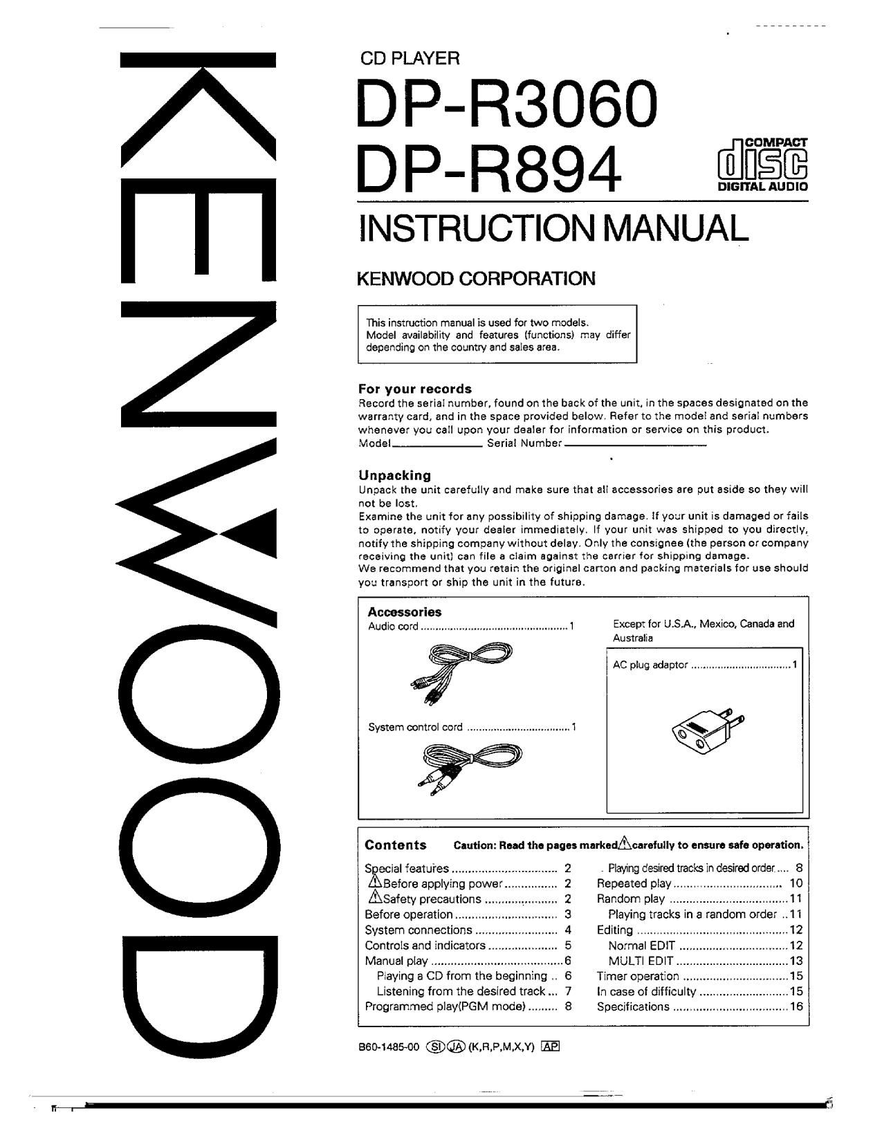
Kenwood DPR 894 Owners Manual

This is the 16 pages manual for Kenwood DPR 894 Owners Manual.
Read or download the pdf for free. If you want to contribute, please mail your pdfs to info@audioservicemanuals.com.

Page: 1 / 16
left right
Kenwood DPR 894 Owners Manual

Extracted text from Kenwood DPR 894 Owners Manual (Ocr-read)


Page 1

IOOMNE

CD PLAYER

DP-R3060 m
DP-R894 @flgfi
NSTRUCTION MANUAL

KENWOOD CORPORATION

This instruction manual is used for two models.
Model availability and features (iunctions) may differ
depending on the country and sales area.

For your records

Record the serial number, found on the back of the unit] in the spaces designated on the
warranty card and in the space provided below, Refer to the model and serial numbers
whenever you call upon your dealer lor information or service on this product.
Model__- Serial Number

Unpacking

Unpack the unit carefully and make sure that all accessories are put aside so they \Nlli
not be lost.

Examine the unit for any possibility of shipping damage. If your unit is damaged or fails
to operate. notify your dealer immediately. If your unit was shipped to you directly,
notifythe shipping company without delay. Only the consignee (the person or company
receiving the unit} can file a claim against the carrier for shipping damage.

We recommend that you retain the original carton and packing materials for use should
you transport or ship the unit in the future.

Accessories
Audio cord. Except for U.S.A., Mexico. Canada and

Australia

AC plug adaptor

Contents Cautlon: Road the page: markudAcarefully to ensure safe operation. i

S ccial features ........ 2 . Playing desired tracks in desired order 8
Before applying power .. 2 Repeated play. . 10
Safety precautions .. .. 2 Random play 11

Before operation... .. 3 Playing tracks in a random order ..11

System connections ., 4 Editing .............................................. 12

Controls and indicators 5 Normal EDIT

Manual play. 6 MULTI EDIT.

Playing a CD from the beginning 6 Timer operation
Listening from the desired track 7 In case of difficulty
Programmed play(PGM mode) . 8 Specifications .....

860-1485-00 @®(K,R,P,M.X,Y) m

Mi

Page 2

Special features

MULTI EDIT ................................................................................

Adoption oi mechanism that enables

disc changing even during Playback .......................................

Programmed play

Before applying power

Units are designed for operation as follows.

U.S.A., Mexico and Canada
U.K. and Australia .....
Europe [Except for UK.
Other countries ......

120 V only

.......... 110-120 I 220-240 V switch

A Caution: Read this page carefully to ensure safe operation.

....Several CD5 can be edited and recorded on 1 tape.

....4 other dist: can be changed not only when the unit Is

stopped, but also during playback.

The program mode allows you to play desired tracks in the
order you want to hear them. A maximum of 32 selections
can be entered In memory.

For the United Kingdom

Factory fitted moulded mains plug

1 . The mains plug contains a fuse. For replacement, use cniva13~Amp
ASTAaopr'oved (BS1362) fuse.

2. The fuse cover must be refitted when replacing the fuse in the '
moulded plug.

3. Do not out off the mains plug from this equlpmerrt. lithe plug fitted
is not suitable for the power points in your home or the cable is too
short to reach a power point, then obtain an appropnata safety
approved menslon lead or adapter. or consult your dealer

if nonetheless the mains plug is cut off, remove the fuse and
dispose of the plug immediately, to avoid a possible shook hazard
by inadvertent oonnectIon to the ma ins supply.

AC voltage selection

This unitoperates on i l O ~120 or 220 , 240 volts AC. The AC voltage
selector switch on the rear panel Is set to the voltage that prevails
in the area to whlch :he unit is shipped. Before connecting the
power cord to your AC outlet, make sure that the setting position of
this swltch matches your line voltage. If not, it must be set to your
voltage In accordance with the following directlon.

AC voltage selector switch

Move switch lever to match your line voltage with
a small screwdriver or other pointed toolt

Note:
Our warranty does not cover damage caused by excessive IIne
voltage due to improper setting oi the AC voltage selector switch.

Safety precautions

WARNING: TO PREVENT FIRE OR ELECTRIC SHOCK, DO NOT EXPOSE THIS APPLIANCE

TO RAIN OR MOISTURE.

_AUTION

RISK or El some sweet:
no nor cIPEM

A A

CAUTION. TO REDUCE THE RISK OF ELECTRIC SHOCK. DO NOT REMOVE
COVER (OR BACK). NO USER-SERVICEABLE PARTS INSIDE. REFER SER-
VICING TO QUALIFIED SERVICE PERSONNEL.

THE LIGHTNING FLASH WITH ARROWHEAD SYMBOL. WITHIN AN EOUILATERAL TRIANGLE.
IS iNTENDED TO ALERTTHE USER TO THE PRESENCE OF UNlNSULATED "DANGEROUS VOLV
TAGE WITHIN THE PRODUCTS ENCLOSURE THAT MAY BE OF SUFFICIENT MAGNITUDE
TO CONSTJUTE A RISK OF ELECTRIC SHOCK TO PERSONS.

THE EXCLAMATION POINT WlTHlN AN EQUILATERAL TRIANGLE IS INTENDED TO ALERT THE
USER TO THE PRESENCE OF IMPORTANT OPERATING AND MAINTENANCE (SERVICING) IN-
STRUCTIONS IN THE LITERATURE ACCOMPANYING THE APPLIANCE.

2 BP-BsDSD/DPREA (En)

m

Page 4

System connections

Make connections as shown below. When connecting the related system components, refer also to the instruction

manuals of the related components.

Do not plug in the power lead until all connections are completed.

m Cassette deck
0 III
E]
0:51 °

gal-5:40

-l--O

System control cord

(optional)

.0

Amplifier or receiver

Audio cord

CCRS

By connecting the SYSTEM CONTROL terminal of this unit with the
' EXQ ' SYSTEM CONTROL terminal of a KENWOOD cassette deck.
CCRS recording can be carried out.

The CCRS function is used when recording from a CD to a tape in a
cassette decic and operates to adlust the cassette decks recording
level to the optimum setting according to "fine playing level of the CD.
For details on the CORE function. refer to the instruction manual
provided with your cassette deck,

System control connection

When connected to an amplifier or receiver having KENWOOD
SYSTEM CONTROL terminals. system operation such as remote
control is made possible. For details. refer to the instruction manual
of the amplifier or receiver.

if your amplifier or receiver is not equipped with the SYSTEM CON-
TFlOL terminals do not connect anything to any SYSTEM CONTROL
terminals.

Do not connect the unit in any system configuration other than

at O
]:l]Dmn:

0 Be sure to insert the system control cord plugs fully into the
SYSTEM CONTROL terminals.

0 if the system control cord and audio cords are not connected
properly. the automatic system governing remote control and
system functions will not operate

NOiSSI

1. Connect all cords firmiyt If connections are loose, there could be loss of sound or noise produced.
2. When plugging and unplugging connection cords, be sure to first remove the power cord from the AC outlet.
Plugging/unplugging connection cords without removai of the power cord can cause mallunctions or damage to the unit.

ll DP-RSDENDPRSBA [En]

Page 5

Controls and indicators

f

RANDOM indicator
Indicator

ALL indicator

EDIT Indicator
Program mode indicator Music calender (1 ~ 20)

L REPEAT Indlcator

Play indicator -
Pause Indicator

Isa: REPEAT slNaE
a. 5mm: NB 5 7 a a 10:
.: .

1 1 12 1a 14 152
© H E;- 8 H -...?....7...1?..1E_'_.=i9.5
-"4 I
Time counter. Program No.
Disc No. indlcators (SINGLE I TOTAL)

TRACK NO. Indicator

Display
STOP key
EDIT MODE key in
OPEN/CLOSE key
P.MODE key I g] I
CHECK key
Dlsc SKIP key
POWER swltch CLEAR key Dlsc selector kc
~ DISC 5)
-J (:1 I:
I g. .g. ... .... ._= m.

L;_'_. L; [j-
m.
l J
Search keys
(ELIE!)
Disc tray 5MP keys
(IE JED
TIME DISP. key REPEAT kev
RANDOM key
PLAY/PAUSE key

>

DPmueotDin (En) 5

2:!
I