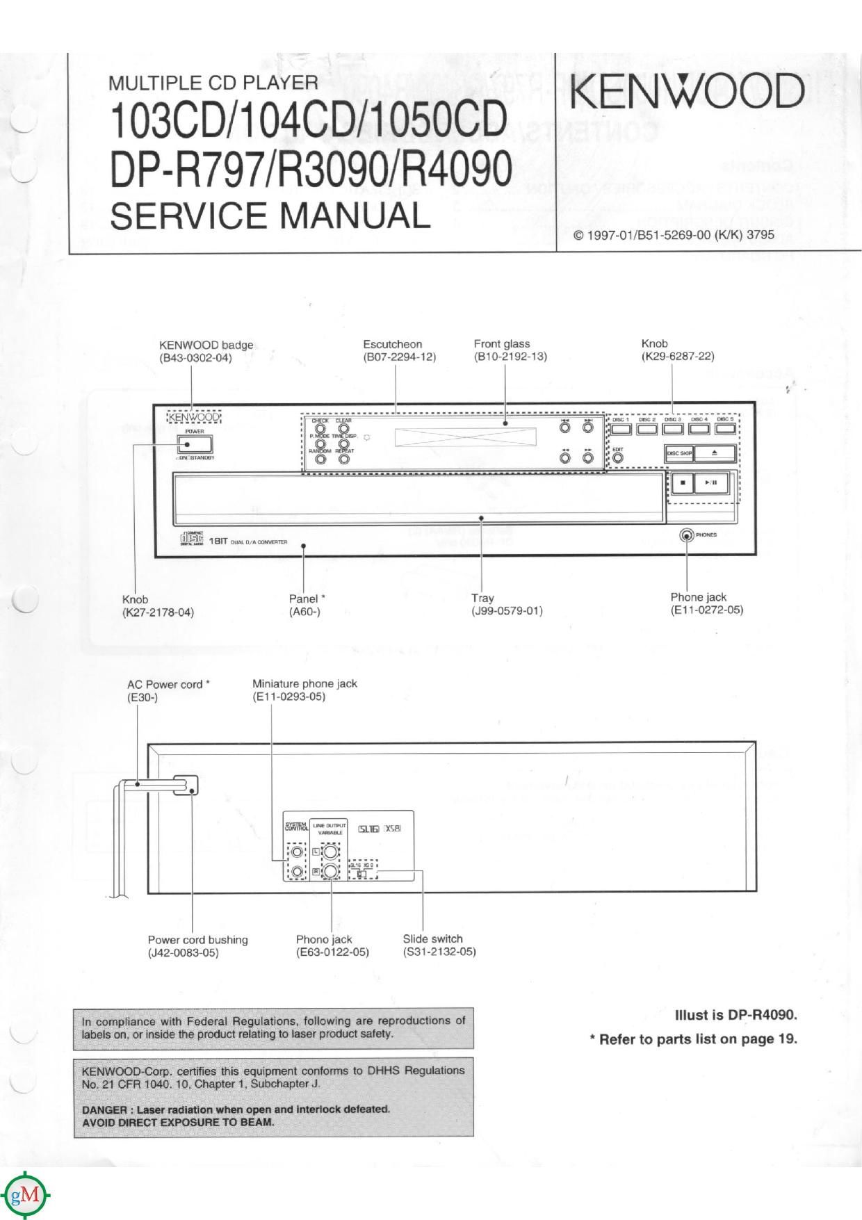
Kenwood DPR 797 Service Manual

This is the 15 pages manual for Kenwood DPR 797 Service Manual.
Read or download the pdf for free. If you want to contribute, please mail your pdfs to info@audioservicemanuals.com.

Page: 1 / 15
left right
Kenwood DPR 797 Service Manual

Extracted text from Kenwood DPR 797 Service Manual (Ocr-read)


Page 4

4090 1030D/104CD/1OSOCD/DP-R797/R3090/R4090

ADJUSTMENT

FIG. FIG. (b)
0 RF signal and TE Signal in test mode (PLAY).
7 o If the diffraction grating has been adjusted correct-
3:; nai ly, the influence of triggering is observed on the
9 TE waveform of approx. 18 )3 s from RF Signal
(a) trigger point. in the form of a projection
7 + vC - 2.2 v
<- VC 2.2 V
CH2
TE1 Signal
(cl
0 RF Signal and TE signal in test mode (Focusmg
(n) servo ON /Tracking servo OFF). (Disc Type 4)
or CH1
(d) RF Signal 0 Adjust TE signal so that the waveform is symmet-
rical in relation to V0. [TE BALANCE)
(e) 4 VC 22V

(VG 2.2V

CH2
TE1 signal

FIG. (u)

0 RF signal in test mode (PLAY).

RF 5'9"? Perform the tangential and focusing offset are

focused into one point on the display. The cross-
ing points above and below the center shall also
be looked clearly.

(FE BALANCE)