Kenwood DPJ 695 Service Manual

This is the 36 pages manual for Kenwood DPJ 695 Service Manual.
Read or download the pdf for free. If you want to contribute, please mail your pdfs to info@audioservicemanuals.com.

Page: 1 / 36
left right
Kenwood DPJ 695 Service Manual

Extracted text from Kenwood DPJ 695 Service Manual (Ocr-read)


Page 1

MULTIPLE COMPACT DISC PLAYER

IP=J695/JiO70/J207O

SERVICE MANUAL

KENWOOD

©1995-8 PRINTED IN KOREA
B51<5071-00 (K) 4010

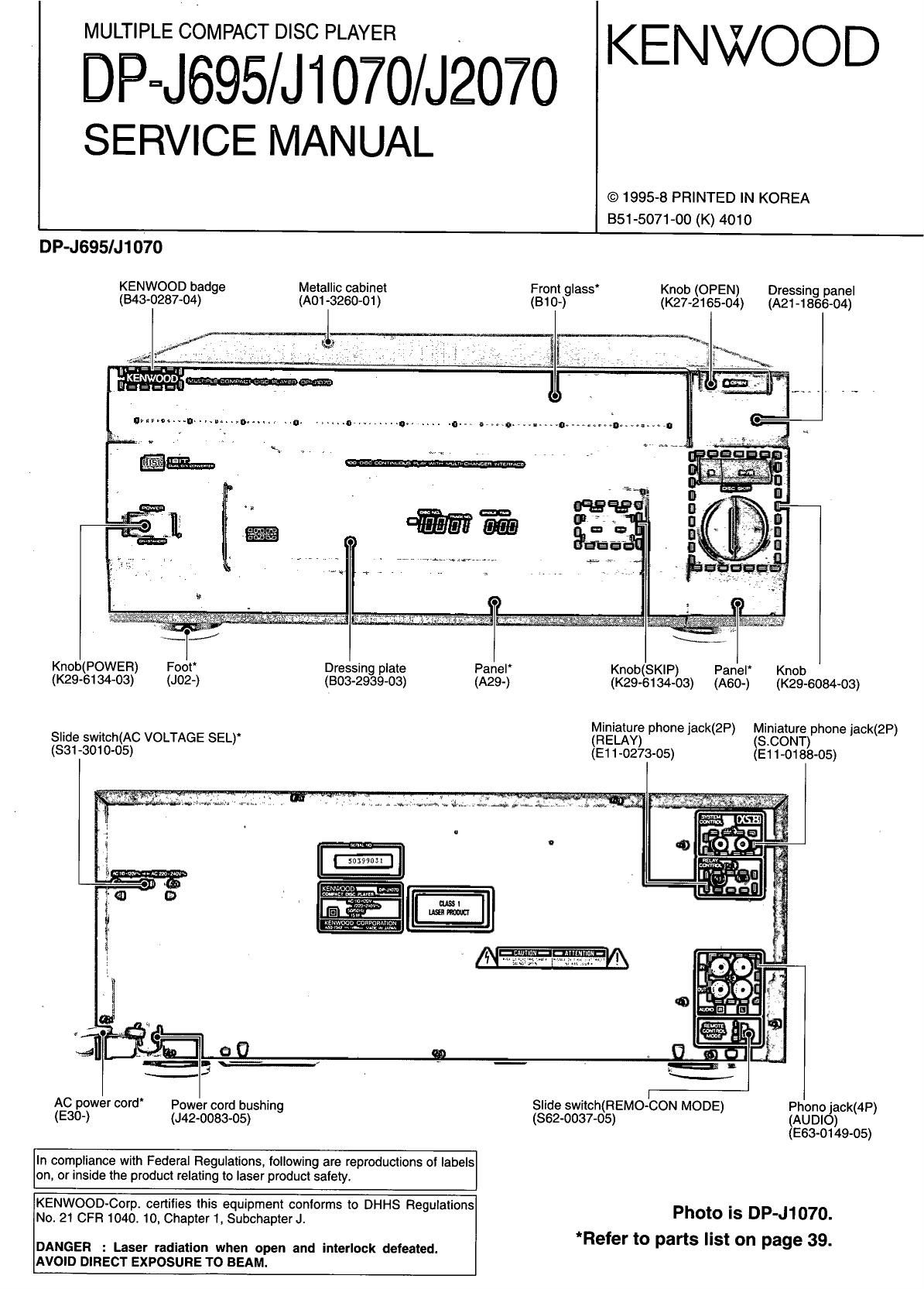
DP-J695/J1070
KENWOOD badge Metallic cabinet
(343-0287-04) (A01 -3260-01)

Dressing panel

Front glass Knob (OPEN)
(B (Am-185604)

10-) (K27-2165-04)

Knob(POWEFt) Foot
(K29-e134-03) (J02-)

Slide switch(AC VOLTAGE SEL)
(331-3010-05)

Dressing plate Panel
(B03-2939-03) (A29-)

Knob(SKlF') Panel Knob
(K29-6134~03) (A60-) (K296084433)

Miniature phone jack(2P) Miniature phone jack(2P)
S CONT

(RELAY) .
(E1 1-0273-05) E1 1-0133-05)

AC Power cord' Power cord bushing
(530-) (J42-0083-05)

In compliance with Federal Regulations. following are reproductions of labels
on, or inside the product relating to laser product safety.

KENWOOD-Corp. cerlilies this equipment conlorms to DHHS Regulations
No.21 CFR 1040. 10, Chapter 1. Subchapter J.

DANGER : Laser radiation when open and interlock defeated.

AVOID DIRECT EXPOSURE TO BEAM.

Slide switch(FIEMO~CON MODE) Phono jack(4P)
(862-0037-05) (AUDIO)
(E63-0149-05)

Photo is DP-J1070.
*Refer to parts list on page 39.

Page 2

DP-J695/J1070/J207O

CONTENTS I ACCESSORIES

EXTERNAL VIEW(DP- J2070) ......
CONTROLS ...............
REMOTE CONTROL OPERATION
DISASSEMBLY FOR REPAIR ...........
BLOCK DIAGRAM ...........
CIRCUIT DESCRIPTION.
MECHANISM OPERATION DESCRIPTION ..

.20

ADJUSTMENT.
PC BOARD ..
SCHEMATIC DIAGRAM .
EXPLODED VIEW(MECHANISM)
EXPLODED VIEW(UNIT)...
PARTS LIST ...........
SPECIFICATIONS

Refer to the following service manual, if detailed description about items in the table below is needed.

Ref No. IC Name Reference SIM Page *1
rcr ch173230 DP.ME9 9,10 RC-P0201 A70-1013-15 DP-J207O KPYXTEG
rc2 CXDZSOOBQ DP-MA5/MA9 17,13 RC-F0201 A70-1040-05 DP-J2070 M
m cxozsrzAQ DP-Rso7o 7,8 Fro-P0100 A70-1014~15 DP-J695/J1070 KRPYX
FtC-POtOO A70~1041~05 DP-J695/J1070 M
Accessories
r V

7 riflnernoteAfiieA 7 7 7 77 fifAAAA
(wo1-oa79-05)

KENWOOD

Remote control unit (1)

l I ll

Battery cover : (A09-0303-08)

AATudio cord(1)
(E30-0505-05)

SfitEm control cordfi l.
(530-2733-05)

AC Plug adaptor (1)
(ens-011505) M type only

Removing the transport screws

Before using the unit, remove the 5 red transport screws
(long x 2, medium x 2, short x 1) on the rear panel.

The screws can be removed by rotating in the directions of the arrows.
After removing, be sure to retain the screws in a plastic bag. etc. They will
be required the next time the unit is transported.

Before transporting the unit again, remove all discs from the rack, switch
the power OFF and attach screws to their respective transport fixing
holes.

' This unit incorporates precision mechanisms. Avoid
applying shock to the unit after the transport screws have

Note been removed. Shock may cause malfunction of the
mechanisms.

Screwdriver
or coin

Transport screws
imediuml

Transport
screws
(long)

screw
Isholll

Beware of condensation

When water vapor comes into contact with the surface of cold
material, water drops are produced

If condensation occurs] correct operation may not be possible, or the
unit may not function correctly.

This is not a malfunction, however, and the unit should be dried.
(To do this, turn the POWER switch ON and leave the unit as it is for
several hours.)

Be especially careful in the following conditions:

0 When the unit is brought from a cold place to warm place. and there
is a large temperature diflarence.

I When a heater starts operating,

I When the unit is brought from an airconditioned place to a place of
high temperature with high humidity.

o when there is a large difference between the internal temperature of
the unit and the ambient temperature, or in conditions where
condensation occurs easily.

Page 16

DP-J695/J1070/J2070

CIRCUIT DESCRIPTION

3. BTL Driver : BA6198FP (X32- A/9, IC3)
3-1 Pin layout

GND

N
no

IN4

IN4'

II 0UT1-B
E OUTt-A OUT4-B
E |N1 OUT4-A
[Z RESET
5 REG-B
I: Q.
E REGOUT LL VFtEFIN
m .
E MUTE O)
,_
IE GND (0
<
IE |N2 CD
E |N2
IE OUT2-A OUTS-A
IE OUT2-B OUTS-B
IE GND ,.OEIN:A,
E OPOUT OPIN-B

VCC

VCC

|N3'

|N3

3-2 Pin description

No. Name Description No. Name Description
1 OUT1 -8 CH1 negative output terminal 15 OPIN-B OP. amp. (-) input terminal
2 OUT1-4 CH1 positive output terminal 16 OPlN-A OP. amp. (+) input terminal
3 |N1 CH1 gain-adjustment input terminal 17 OUTS-B CH3 negative output terminal
4 RESET Reset output terminal 18 OUTa-A CH3 positive output terminal
5 REG-B External regulator Tr. base connecting terminal 19 ms CH3 input terminal
6 REGOUT External regulator Tr. collector connecting terminal (output) 20 IN3' CH3 gain-adjustment input terminal
7 MUTE Mute control terminal 21 VCC VCC
8 GND GHD terminal 22 VCC VCC
9 IN2 CH2 gain-adjustment input terminal 23 VREFIN Relerence amp. input terminal (bias)
10 |N2 CH2 input terminal 24 IN4' CH4 gainvadiustment input terminal
11 0UT2-A CH2 positive output terminal 25 |N4 CH4 input terminal
12 0UT2-B CH2 negative output terminal 26 OUT4-A CH4 positive output terminal
13 GND Sub straight GND 27 OUT4~B CH4 negative output terminal
14 OPOUT 0P. amp. output 28 GND Sub straight GND

Note: The positive output and the negative output mean the polarity for the input.

16

(Input "H"->positive output : "H",negatlve output : " L")