Kenwood DPG 7 Service Manual

This is the 14 pages manual for Kenwood DPG 7 Service Manual.
Read or download the pdf for free. If you want to contribute, please mail your pdfs to info@audioservicemanuals.com.

Page: 1 / 14
left right
Kenwood DPG 7 Service Manual

Extracted text from Kenwood DPG 7 Service Manual (Ocr-read)


Page 1

COMPACT DlSC PLAYER KE NWOO D
DP-G7

SERVICE MANUAL
(up-705)

is?» 1996-4/851-5176-00 (K/K) 2602

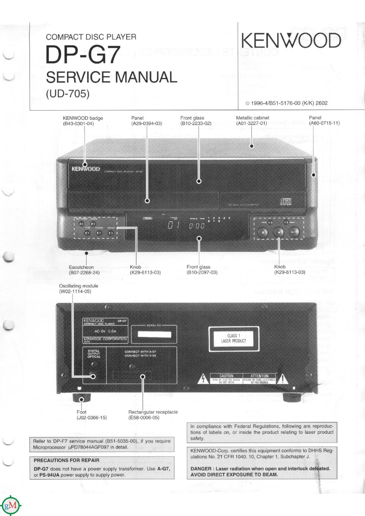
KENWOOD badge Panel Front glass Metallic cabinet Panel
(E43-0301-O4) (A29-0394-03) (310-2233-02) (A01 ~3227v01) (A60-O715-11)
l

Escutcheon Knob Front glass Knob
(307-2268-24) (K29-61 13-03) (81072097703) (K296113013)

Oscillating module
(W02-1114-05)

ummr
Oumr cowuacr wnu
OPTICAL CONNm wlm

l l .

Foot
(JOE-03664 5)

Rectangular receptacle
(Esa-oooa-os)

In compliance with Federal Regulations, iollowing are reproduc-
tions of labels on, or inside the product relating to laser product

Refer to DPF7 service manual (351-5035-00). if you require safe!-

Microprocessor uPD7BO44AGF097 In detaili

KENWOOD-Corp cenilies this equipment conforms to DHHS Reg-

. Ft 1 . 1 h t .
PRECAUTIONS FOFI REPAIR ulatrons No 21 CF 040 O. C ap er 1, Subchapter .1 .
DP-G7 does not have a power supply transformer. Use A-G7, DANGER : Laser radiation when open and interiock de ted.
or PS-MUA power supply to supply power. AVOID DIRECT EXPOSURE TO BEAM. 1

Page 2

DP-G7

ADJUSTMENT

i
INPUT SET- PLAYER ALIGNMENT
No. ITEM TINGS OUTPUT SETTINGS SETTINGS POINTS ALIGN FOR FIG.
On the power from
. . 0.06 to 015 mW
Eva'flfe55fl'1rg :3: (When the diffraction
Apply the sensor section AC ON. (Test mode] $3,223 fiiaogzcg:
1 LASER POWER - of optical power meter Press the DOWN - levgel of 1 0 V _ or (a)
on the pickup lens. key. then-confirm more and 1h: TE
that theoglnsplay '5 (servo open) level of
0.6 Vp-p or more. the
pickup is acceptable.)
. Set the unit to test
Connect an oscrlloscope
2 TRACKING ERROR Test disc as follows. diffieflfizéhgafik TE BALANCE scam/'32:? (c)
BALANCE Type 4 CH11RF (CN3 pin 1) k 4th 1. th VR2 pp 1 p
CH2:TE (CNS pin 6) a" .9" cm. "I .3 ms
the display IS 03 ,
Connect an oscilloscope Smegg: $2,125: :3
FOCUS ERROR Test disc as follows. ' FE BALANCE .
3 BALANCE Type 4 CH12RF (CNS pin 1) Raw/123w? I VR1 Opt'mur" eye Pane (d)
CH2:TE (CN3 pin 6) "m . .. 9.. 'Sp 3"
IS 05 .
Test disc ,
A [Type 4 I f cennserg f 2.: tr? CNS 5:22? 32:5: 11:? TRACKING T VTVM h Id
pp y srgna 0 pm - o w IC you _ we 5 5 cu
4 TRACKING GAIN 1.0 kHz, connect an oscilloscope 15m: aliektgfsn Izmis (Bi/2': read the same value. (e)
SDmVrms to or AC voltmeters. 05. p y
CNS pin 56. '
Note:

Type 4 disc: SONY YEDS-18 Test Disc or equivalent.
LPF: Around 47 kn+ 390 pF or so.
Step 1~4 are in Test Made.

(a) Laser power

Pickup

0,06 \ 0.15

Optical power meter

(e) Tracking gain

1.0 kHz
50 mVrms

CNS