Kenwood DPFR 6010 E Service Manual

This is the 18 pages manual for Kenwood DPFR 6010 E Service Manual.
Read or download the pdf for free. If you want to contribute, please mail your pdfs to info@audioservicemanuals.com.

Page: 1 / 18
left right
Kenwood DPFR 6010 E Service Manual

Extracted text from Kenwood DPFR 6010 E Service Manual (Ocr-read)


Page 1

CBE206/DEFibOlOl-MK) 2P ( 98.4 2410113934 y UN 2 /\
\, /

5535555316010 R6010E KENWOOD

SERVICE MANUAL

©1998-3/BS1-5418-00 (K/K) 3430

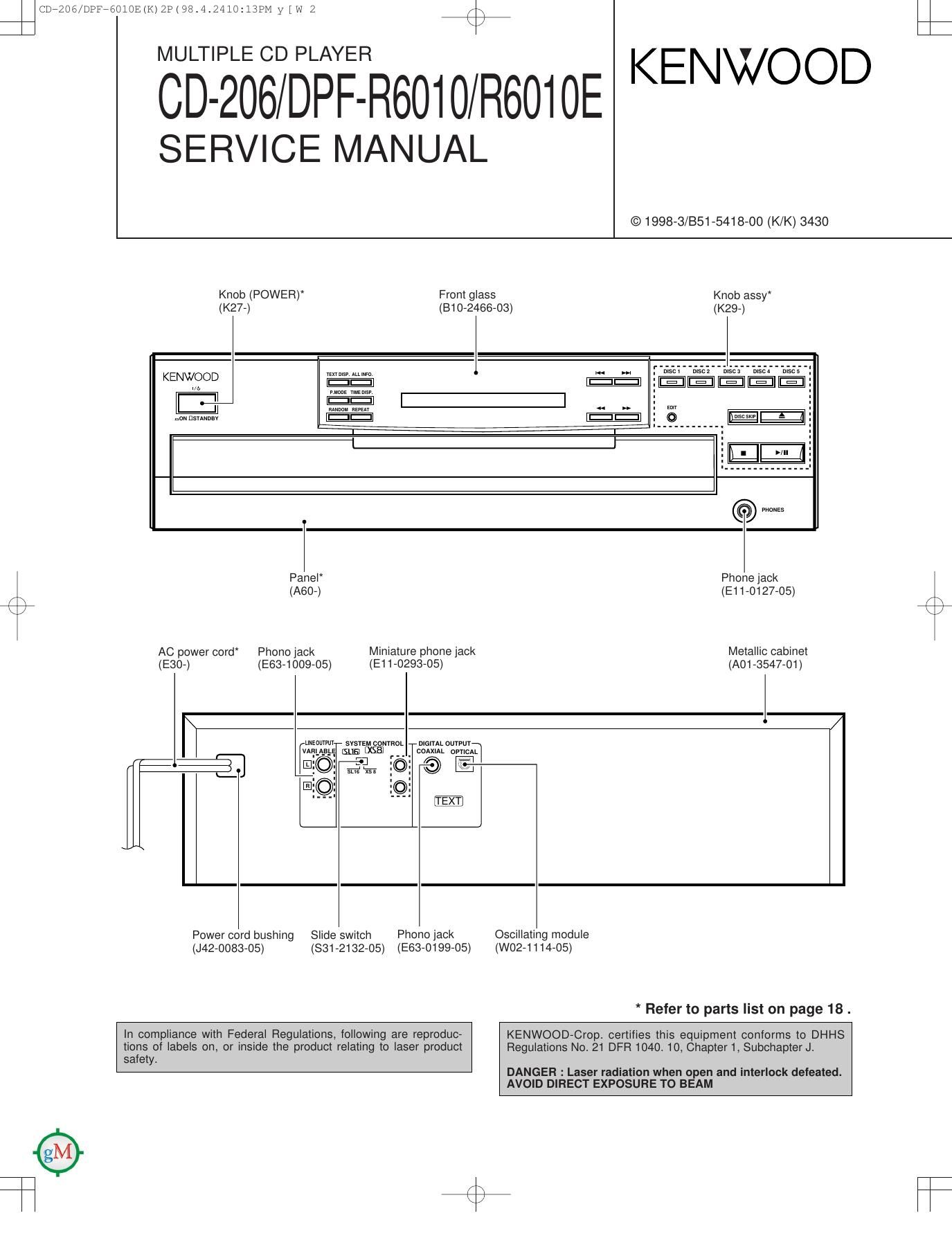
Knob (POWER) From glass Knob assy
(K27-) (810-2468-03) (K29-)


KENWEJOD mums» mm
nounsnwav mm m"
\~/
I
-I
@ Wis
Panel Phone jack
77 (A80-) (E11-0127-05)
/ \
x 2
AC power cord Phono jack Miniature phone jack Metallic cabinet
(E30-) (E63-1009-05) (E11-0293-05) (A01 {5547-01)
system coNYRoL mm oumn
_ _, ism; f__ . COAXIAL onion
41
EXT
Power cord bushing Slide switch Phono lack Oscillating module
(J42-0083-05) (831-2132-05) (E63-0199-05) (WO2-1114-05)

* Refer to parts list on page 18 .

KENWOOD-Cropt certifies this equipment conforms to DHHS

in compliance with Federal Regulations, following are reproduc-
Regulations No. 21 DFR10401 10, Chapter 1, Subchapter J.

tions of labels on, or inside the product relating to laser product
safety.

DANGER : Laser radiation when open and interlock defeated.
AVOID DlFlECT EXPOSURE TO BEAM

Page 2

CDi206/DPFibOlOE(K) 2P ( 9814.2410113'934 y [W 3

CD-206/DPF-R6010/R6010E

CONTENTS / ACCESSORIES


Contents

CONTENTS / ACCESSORIES ................................... 2 SCHEMATIC DIAGRAM ........................................... 11
CIRCUIT DESCRIPTION .......... ....3 EXPLODED VIEW ......... 16
ADJUSTMENT ................. 6 PARTS LIST ................................ 18
PC BOARD ................................................................. 7 SPECIFICATIONS ....................................... Back cover

Accessories

r N

System control cord (1)
(E30-2733-05)

Audio cord (1)
(E30-0505-05)

Batteries (RS/AA) (2)

AC plug adapter (1)
(E03-0115-05) : M type only

Remote control unit (1)
(A70-1134-05) : RC-P0601

Battery cover: (A09-0356-08)

QEHO EU "0 0 m0 30 %0 IO 10%
§g~0 m0 ~U m0 0 <0 -_0 i0 :0 fig
gooooo%$%§§

$%%%@%%%%

Page 6

CDi206/DPFi60lOE(K) 2P ( 98t4.24lO:l4?M y [W 10

CD-206/DPF-R6010/R6010E

4%

ADJUSTMENT

No ITEM INPUT OUTPUT PLAYER ALIGNMENT ALIGN FIG
' SETTINGS SETTINGS SETTINGS POINTS FOR '
Step 1~4 are in TEST MODE
While pressing the On the power from
RANDOM key, turn 0.08 to 0.15 mW,
Apply the sensor section the AC ON. (Test when the diffraction
1 LASER POWER 7 of optical power meter mode) Press the 7 grating is correctly (a)
on the pickup lens. PLAY/PAUSE key, aligned with the RF
then confirm that the level of 1.0 Vp-p or
display is "03". more.
Connect an oscilloscope Press the
2 TRACKING ERROR Test disc as follows. PLAY/PAUSE key, TE BALANCE symgeggylgfigefl
BALANCE Type 4 CH1 : RF (CN2 pin 1) then confirm that the VR2 We mm W
CH2 : TE (CN2 pin 6) display ls "03".
Connect an oscilloscope Press the
3 FOCUS ERROR Test disc as follows. PLAY/PAUSE key, FE BALANCE Optimum eye pat-
BALANCE Type 4 CH1 : RF (CN2 pin 1) then confirm that the VR1 tern
CH2 : FE (CN2 pin 2) display is "05".
Test disc
Type 4 Connect a LPF to CN2 Press the TRACKING Two VTVMs should
Apply signal of pin 5-6 to which you PLAY/PAUSE key,
4 TRACKING GAIN 1.2 kHz, connect an oscilloscope then confirm that the (32"? readvtgTIEesame (e)
SOmVrrns to or AC volfmeters. display ls "05". '
CN2 pin 5-6.
Note:
/\ Type 4 disc : SONY YEDS-18 Test Disc or equivalent.
c LPF: Around 47 kfl+ 390 pF or so.
(a) Laser power (e) Tracking gain
CN2
0.08~0.15 mW

R

Pickup

[_I
BE

Optical power meter

1.2 kHz
50 mVrms

®
6)
o
@
o
o