Kenwood DPFR 3030 S Service Manual

This is the 19 pages manual for Kenwood DPFR 3030 S Service Manual.
Read or download the pdf for free. If you want to contribute, please mail your pdfs to info@audioservicemanuals.com.

Page: 1 / 19
left right
Kenwood DPFR 3030 S Service Manual

Extracted text from Kenwood DPFR 3030 S Service Manual (Ocr-read)


Page 1

CD7403(K)COVER1,1P( 9912.7 4:06 PM «Ks/2

r\
\/

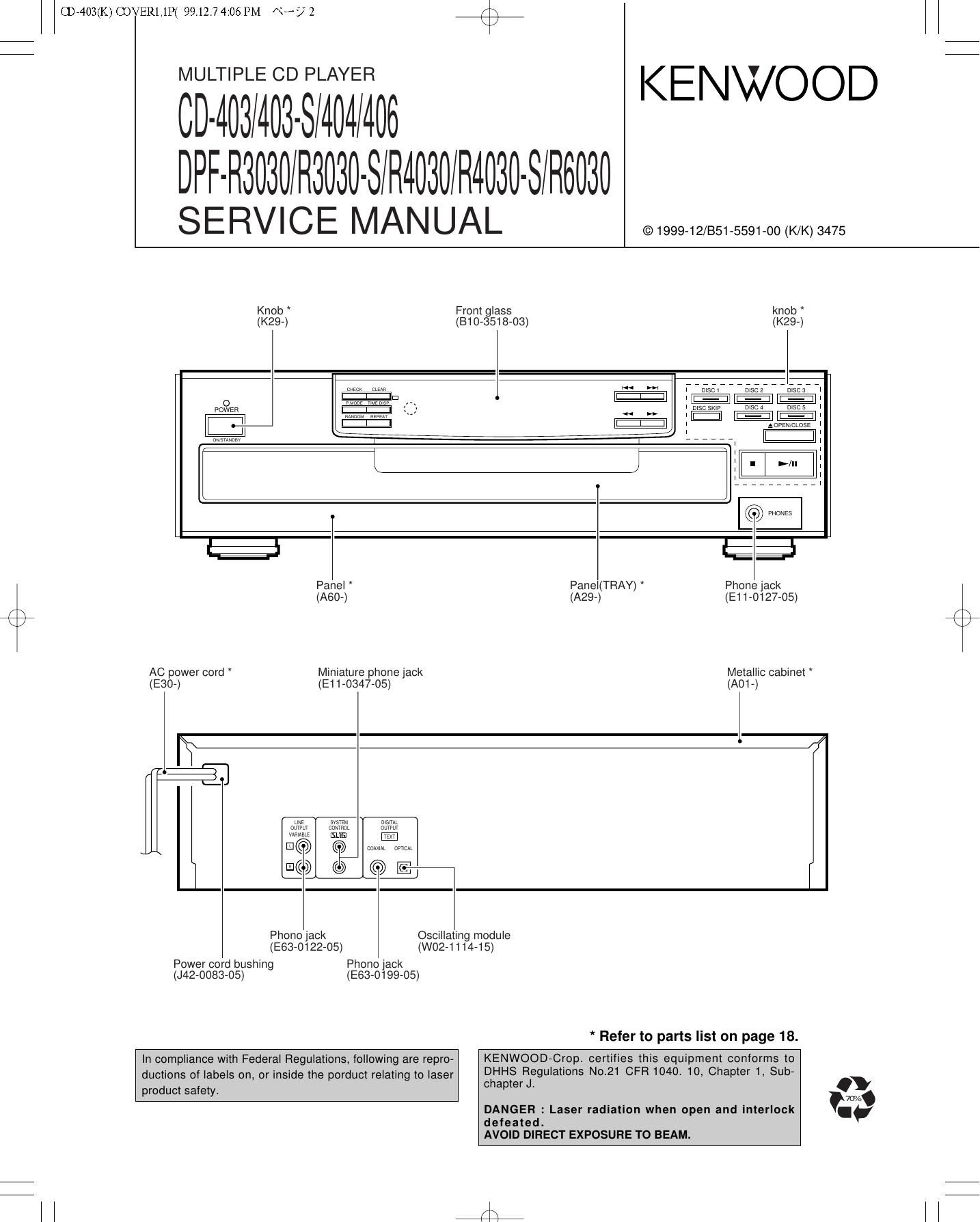
MULTIPLE CD PLAYER

(DAWMWSWWM6

KENWOOD

Drammmmmsmmmmmmsmwm

SERVICE MANUAL

©1999-12/851-5591-00 (K/K) 3475

Knob
(K29-)

Front glass
(810-3518-03)


u
o
powgn


'\
(Q was

Panel

(A60-)
AC power cord Miniature phone jack
(530-) (E11-0347-05)

Panel(TRAY) *
(A29-)

é;

Phone jack
(E11-O127-05)

Metallic cabinet
(A01 -)

h


svsrm
whim

Lsua

@
©©E

max at amt

Phono jack Oscillating module

(E63-0122-05) (W02-1

Power cord bushing Phono jack
(J42-0083-05) (E63-O199-05)

114-15)

* Refer to parts list on page 18.

In compliance with Federal Regulations, following are repro-
ductions of labels on, or inside the porduct relating to laser
product safety.

chapter Jr

defeated.
AVOID DIRECT EXPOSURE TO BEAM.

KENWOOD-Crop. certifies this equipment conforms to
DHHS Regulations Not21 CFR 1040. 10, Chapter 1, Sub-

W/o
DANGER : Laser radiation when open and interlock I

fii

Page 2

CD7403(K) COVER1,1P( 99.12] 4:06 PM \°-A7 3

we
CD-403/403-S/404/406/DPF-R3030/R3030-S/R4030/R4030-S/R6030

CONTENTS / ACCESSORIES / CAUTIONS

Contents
CONTENTS / ACCESSORIES / CAUTIONS.... 2 SCHEMATIC DIAGRAM ..
CIRCUIT DESCRIPTION .................................. ....3 EXPLODED VIEW ...........
ADJUSTMENT.... ....5 PARTS LIST ..............
PC BOARD ......... .. 6 SPECIFICATIONS ..... Back cover
Accessories
I \
Audio cord (1) System control cord (1) AC plug adaptor (1)
(E30-0505-05) (E30-2816-05) (E03-0115-05)
I
Use to adapt the plug on the power cord
. , to the shape of the wall outlet.
Remote control unit (1) Batteries (RB/AA) (2) (Accessory only for regions where
(Except for CD-403/DPF-Fl3030) (Except for CD-403/DPF-Fl3030) use is necessary_)
(A7D-1339-05): RC-P0711
@g
Battery cover (A09-0356-08)
\ J
Cautions

Operation to reset

The microcomputer may malfunction (impossibility to operate, erroneous

display, etc.) when the connection cords are unplugged while the unit is
ON or due to an external factor. In this case, execute the following
method to reset the microcomputer and return it to normal condition.

Unplug the power cord from the power socket and plug the power
cord into the socket again.

Page 5

F\
\/

CD74031NTERNET 99.12] 4:36PM \'-/6

CD-403/403-S/404/406/DPF-R3030/R3030-S/R4030/R4030-S/t6030

ADJ

USTMENT

INPUT OUTPUT PLAYER ALIGNMENT
N°' EM SETTINGS SETTINGS SETTINGS POINTS AL'GN FOR F'G-
Open the tray (Normal mode), then turn the power olf.
While pressing the On the power from
A 1 the sensor REPEAT key, turn 0.08 to 0.15 rnW,
8:39; of Optical the Ac ON. (Test when the diffraction
1 LASER POWER mode) Press the grating is correctly (a)
poweirckmefer:sr the PLAY/PAUSE key, aligned with the RF
It Up ' then confirm that the level of 1.0 Vp-p or
display is "03". more.
1. Load a disc on disc 1 tray.
2. Turn the power 0.
3. While pressing the REPEAT. key, turn the power ON to enter the Test mode.
Connect an Press the
1 FOCUS ERROR Test disc oscilloscope as PLAY/PAUSE key, FE BIAS O timum e e attern
BIAS Type 4 follows. then confirm that the VR1 P y p
CH1 : display is "05".
Connect the DC Press the
2 LASER CURRENT Test disc voltmeter to PLAY/PAUSE Key, _ 0 5+0 2V
CHECK Type 4 CN3(pin3 and 4) then conlirm that the ' '

on X32.

display is 03 or 05.

Note:

Type 4 disc : SONY YEDS-18 Test Disc or equivalent.
LPF: Around 47 kfl+ 390 pF or so.
Step 1~4 are in TeSt Mode.

(a) Laser power

R

Pickup

0

.08~O.15 mW

L]
BE

Optical power meter