Kenwood DPFK 6010 V Service Manual

This is the 24 pages manual for Kenwood DPFK 6010 V Service Manual.
Read or download the pdf for free. If you want to contribute, please mail your pdfs to info@audioservicemanuals.com.

Page: 1 / 24
left right
Kenwood DPFK 6010 V Service Manual

Extracted text from Kenwood DPFK 6010 V Service Manual (Ocr-read)


Page 1

oppKeOlowx) COVER1,1(98.12.1010154 y [w 2

+
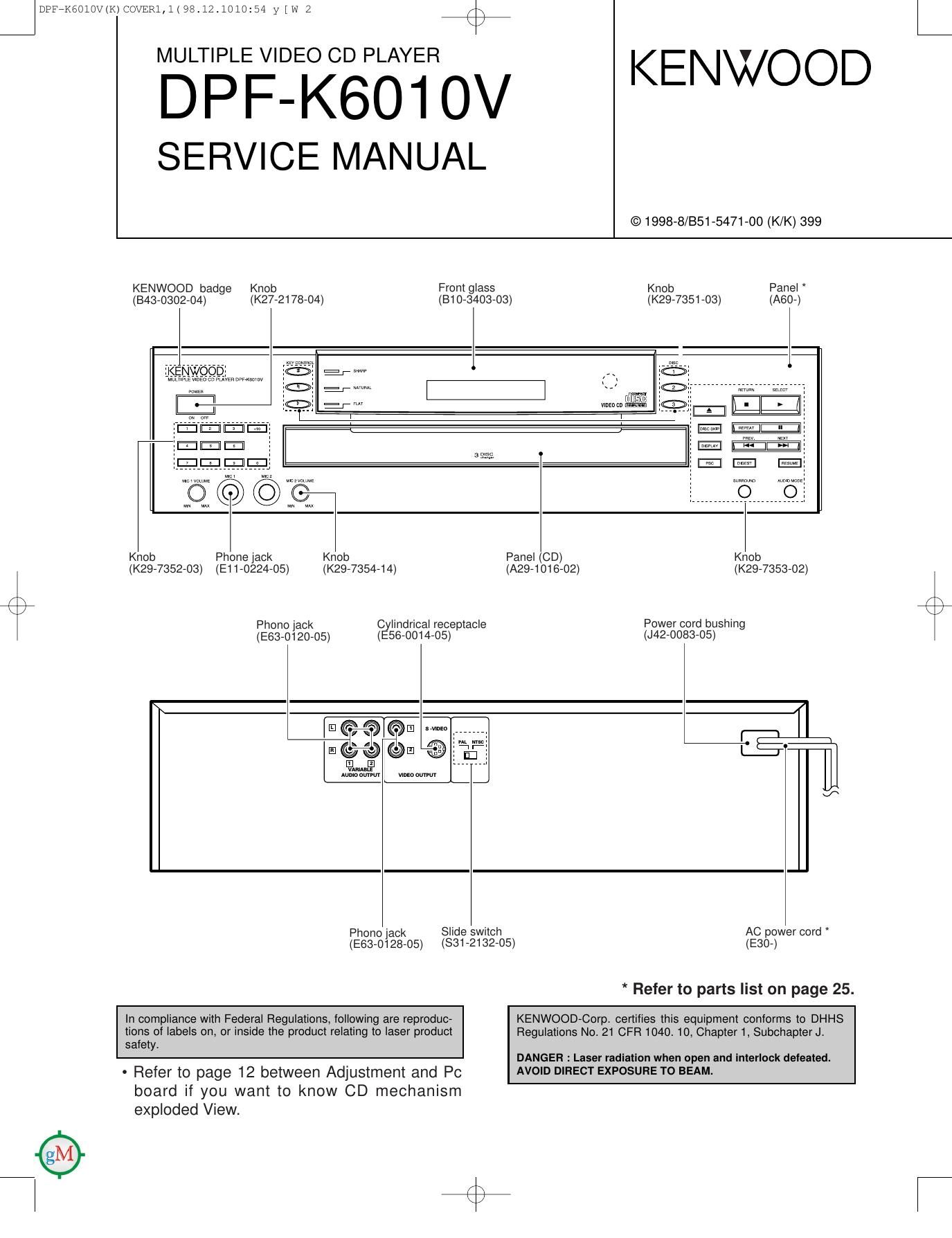
MULTIPLE VIDEO CD PLAYER

DPF-KSOIOV

SERVICE MANUAL

From glass
(810-3403-03)

Knob
(K27-2178-04)

KENWOOD badge
(343-0302-04)

KENWOOD

© 1998-8/851-5471-00 (K/K) 399

Panel
(A60-)

Knob
(K29-7351-03)

S " nae

VlDEDED _mr1 ,.

3 P135

E.

does

Knob Phone Jack Knob Panel (CD) Knob
(K29-7352-03) (E11-0224-05) (K29-7354-14) (A29-1016-02) (K29-7353-02)
\
K
Phono lack Cylindrical receptacle Power cord bushing
(E63-0120-05) (E56-0014-05) (J42-0083-05)
13
\f
Phono jack Slide switch AC power cord

(E83-0128-05) (831-2132-05)

(E30-)

* Refer to parts list on page 25.

In compliance with Federal Regulations, following are reproduc-
tions of labels on, or inside the product relating to laser product
safety.

- Refer to page 12 between Adjustment and Pc

KENWOOD-Corp. certifies this equipment conforms to DHHS
Regulations No. 21 CFR 1040. 10, Chapter 1, Subchapter J.

DANGER : Laser radiation when open and interlock defeated.
AVOID DIRECT EXPOSURE TO BEAM.

board it you want to know CD mechanism
exploded View.

L

Page 2

DPFPK6010V(K)COVER1,1(98.12.1010154 y [w 3 if

CONTENTS / ACCESSORIES / CAUTIONS

Contents
CONTENTS / ACCESSORIES / CAUTIONS ............. 2 PC BOARD .............................................................. 13
DISASSEMBLY FOR REPAIFL .. SCHEMATIC DIAGRAM .. ....17

BLOCK DIAGRAM ............. EXPLODED VIEW .. .24


CIRCUIT DESCRIPTION PARTS LIST ............ ....25
ADJUSTMENT ......... SPECIFICATIONS ..................................... Back cover
EXPLODED VIEW
Accessories
r W
Audio cord .................. (1) Video cord ................... (1 )
(E30-0505-05) (E30-1427-05) &%§Ig$1a5d_ggt)°r """"""" (I)
4
'1
Use to adapt the plug on the power cord
to the shape of the wall outlet.
(Accessory only for regions where
use is necessary.)
Remote control unit ............. (1)
(A70-1226-O5) : RC-POSlO Battery cover (A09-1104-08)
\ .
K 8 5 Batteries (RO3/AAA) ........ (2)
o t:
a e M
Z g2 9
LU 5
>4 ;
c J
Cautions
Nate related to transportation and ma ve- Operation to reset
ment The microcomputer may malfunction (impossibility to operate,
erroneous display, etc.) when the connection cords are un-
Before transporting or moving this unit, carry out the following plugged while the unit is ON or due to an external factor. In this
operations. case, execute the following method to reset the microcomputer

and return it to normal condition.
1. Turn the unit ON but do not load a disc.

2. Wait a few seconds and verify that the display shown appears.

Set the POWER switch to OFF, and after several seconds,
set the POWER switch back to ON.

II-IIB DI II E L,- 0 Please be aware that resetting the unit will erase all stored informae
tron and return it to the factory settings,

3. Wait until "no disc" is displayed and turn off the unit.

Page 3

DpFrkéolowkmovaRlJi9842101054 y [w 6 if

DISASSEMBLY FOR REPAIR

How to open the tray if not comes out.

(1) From the rear side of the CD mechanism, use a screw driver or the like to turn the friction arm fully counterclockwise.
(2) Pull out the tray front wards by hand when the tray comes just out.

* As for details of items in the below, refer to RXD-F3 service manual (851-5091-00).
(1) How to detach the tray.
(2) How to attach the tray.
(3) Replacing the pickup.


Friction
Arm