Kenwood DPF 2030 S Service Manual

This is the 13 pages manual for Kenwood DPF 2030 S Service Manual.
Read or download the pdf for free. If you want to contribute, please mail your pdfs to info@audioservicemanuals.com.

Page: 1 / 13
left right
Kenwood DPF 2030 S Service Manual

Extracted text from Kenwood DPF 2030 S Service Manual (Ocr-read)


Page 1

DPF71030(K)COVER1,1( 5/10/00 6:20 PM «3? 1 /\
\/

EFF-T1DBEP671E630E/1030-3 KENWOOD

DPF-2030/2030E/2030-S

S E RV I C E MAN UAL ©2000-3/BSl-5603-00 (K/K) 2100

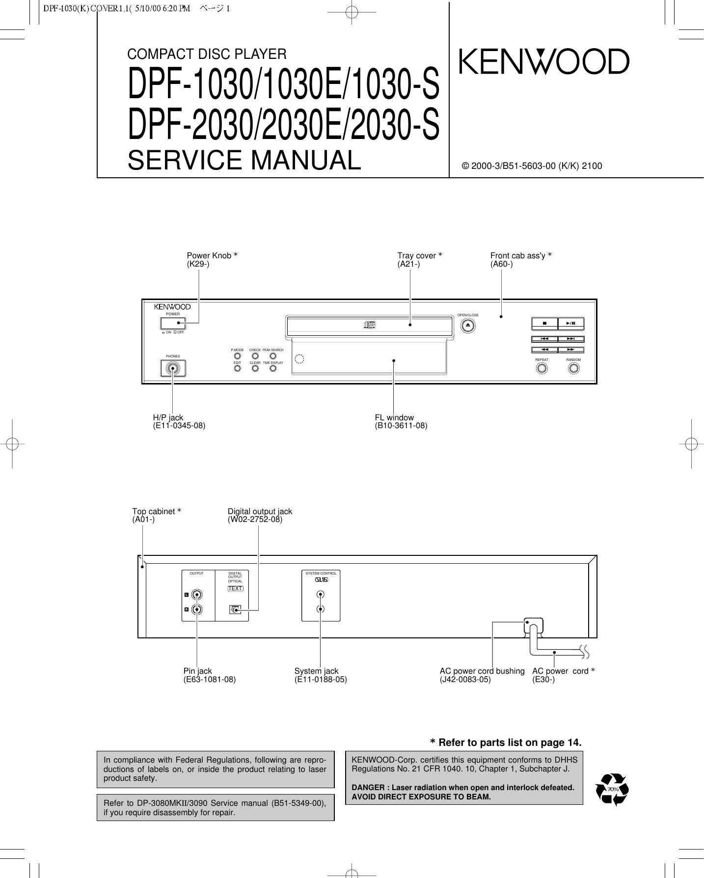
Power Knob * Tray cover * Front cab assy *
(K29-) (A21-) (A60-)
KENWOOD

L ,

l

tun no»

W91: cygc-K».K§um Eng]
9 0 O W1
o 0 Q Q
H/P jack FL window
(E11-0345-08) (B10-3611-08)
/\
K /
Top cabinet * Digital output jack
(A01-) (W02-2752-08)

n mm
nurrur
omen

m

@-

svsizn comm

{SUE}

TLfls

Pin jack System jack AC power cord bushing AEC power cord *
(E63-1081-08) (E11-0188-05) (J42- 0083- 05)

* Refer to parts list on page 14.

In compliance with Federal Regulations, following are repro- KENWOOD-Corp. certifies this equipment conforms to DHHS
ductions of labels on, or inside the product relating to laser Regulations No.21 CFR 1040. 10, Chapter 1, Subchapter J.
product safety. .
DANGER : Laser radiation when open and interlock defeated. 703/3
_ AVOID DIRECT EXPOSURE TO BEAM. I.
Refer to DP-3080MKII/3090 Servrce manual (B51-5349-00),
if you require disassembly for repair

Page 2

DPF71030(K)COVER1,1( 5/10/00 6:20 PM «3? 2 K \

DPF-1030/2030

CONTENTS / ACCESSORIES

Contents

CONTENTS / ACCESSORIES .................................. 2 SCHEMATIC DIAGRAM ............................................ 7
DISASSEMBLY FOR REPAIR.. ..2 EXPLODED VIEW .......... ..
CIRCUIT DESCRIPTION .......... PARTS LIST .......................... 14

ADJUSTMENT .................. .. SPECIFICATIONS ...................................... Back cover
PC BOARD ................................................................ 5
Accessories
r \
Audio cord .................. (1) System control cord ...... (1)

(EGO-291308) (E30-2912-08) AC plug adaptor .............. (1)
, (E03-0115-05)

a}, Use to adapt the ping on the
I power cord to the shape of the
walloutlei.

(Accessory only for regions where
use is necessary.)

Remote control unit ......... (1)
(A70-1414-08) : RC-P0715

(DPF-2030 only) Battery cover : (A09-1190-08)

Batteries (Re/AA) ........ (2)
(DPF-2030 only)

KE NWOOD
REMOTE CONTROL UNlT Fic Him 5

x
u
w

/\ 5

x/ E
I o/'\
E 3i
0 §\,/

\ J

DISASSEMBLY FOR REPAIR

1. How to open tray when tray not come out.

1. Insert the screw driver to left side hole of mechanism ass'y.
2. While pushing the rack gear fully right wards, then the tray pull.

Page 3

\j

1. Pin description of microprocessor

4e

2. Test mode

Pin No. Pin Name l/O Description

1-6 6G-1 G 0 FL grid control port.

7 NC » Unused.
8 VDD » Power supply(+5V).
9-11 - » Connected to ground.
12 C-RESET O DSP signal output.
13 S-MUTE O Muting signal output for system.
14 NC » Unused.
15 TEXT I Text copy detection.
16 - Connected to ground.
17 RESET Hardware reset signal Input.

Tray motor control.

I
18 LB CLOSE O
O

19 LB OPEN Tray motor control.

20 AVSS » Connected to ground.

21 - Connected to ground.

22 PU IN SW Plckup location.

Tray open switch input.

24 CLOSE SW Tray close swnch input.

|
23 OPEN SW |
|
|

25-28 KEYO-3 Key input port.

29 AVDD Power supply(+5V).

30 AVREF » Reference voltage(+5V).
31,32 XT1,2 » Connected to ground.

33 VSS » Connected to ground.
34,35 XO,1 » X'tal 4.19MHZ.

36 WHO I Sub code Q output.

37 COIN 0 Command data to DSP.

38 1SBIT » Unused.

39 HF » Connected to ground.

40 NC » Unused.

41 CQCK O Clock output to DSP.

42 SQOUT I SO data to dsp.

43 RWC O Reading/writing control port.

44 GND » Connected to ground.

45 S BUSY I/O System control data.

46 8 DATA I/O System control status.

Setting the test mode
While pressing the STOP key. press the POWER Switch.

START
FL LIGHT UPALL

Tray open/close enable (display no change)

For move Pickup. up and DOWN key enable only stop mode

Key In PLAY <-

Laser ON , Dlsplay [LD ON]

Key In Play
Focus ON, Display [FS ON]

WITH TIME DISPLAY

Key m STOP When play mode. UP key enable

but only track lump


STOP key enable
ll key In STOP,
return 10 start

47 RMC I Remote control signal input. Test mode WIII be cancelled by pressing the
48 GND , Connected 10 ground. POWER switch key In the stop mode,
49 TRY L/H O Tray motor speed control. 3 Key function in test mode
50 SL- 0 Sled motor control port(reverse). No INPUT KEY FUNCTION DISPLAY
51 SL+ O Sled motor control port(folward). 1 ' PLAY(1ST) LASER ON LD ON
52 VDD * POWe' SUPp'Y(+5Vl- 2 PLAY(2ND) Focusme SERVO ON FS ON
53-59 NC - Unused. 3 PLAY(3RD) PLAY(TRACKING SERVO OFF) Sb Off
60 DRF I CD focus 0K signal Input. 4 PLAY(4TH) PLAY(TRACKING SERVO ON) TNO. And Time
51 NC _ Unused. 5 UP In the stop mode. Moves the pickup slightly
_ .- _- toward the outer position disc. -
62 70 a] 0 FL segment(a J) comm port. When tracking servo is ON, set the track number up.
71 VLOAD ' Power SUpply('30V)' 6 DOWN In the stop mode. Moves the pickup slightly
72,73 k,| 0 FL segment(k,l) controI port. toward the inner position disc. -
74-77 NC » Unused. When tracking servo is ON, set the track number up.
78-80 9979 0 FL grid(BG-7G) control port. 7 STOP Laser oft, focusing servo off, tracking servo 011. All segments
8 OPEN/CLOSE In the stop mode, Tray is opened or closed. All segments

do

NOILdIHOSHG .LlflOHIO

0808/0230 L':|c|(]

5.\/ PM 069 00/01/5 lIIHEIAODOImEOIfldG

E