Kenwood DPF 2010 Service Manual

This is the 14 pages manual for Kenwood DPF 2010 Service Manual.
Read or download the pdf for free. If you want to contribute, please mail your pdfs to info@audioservicemanuals.com.

Page: 1 / 14
left right
Kenwood DPF 2010 Service Manual

Extracted text from Kenwood DPF 2010 Service Manual (Ocr-read)


Page 1

ppreloloscmx) COVERl,l(98t12.9l7:48 y [w 2 :r
K

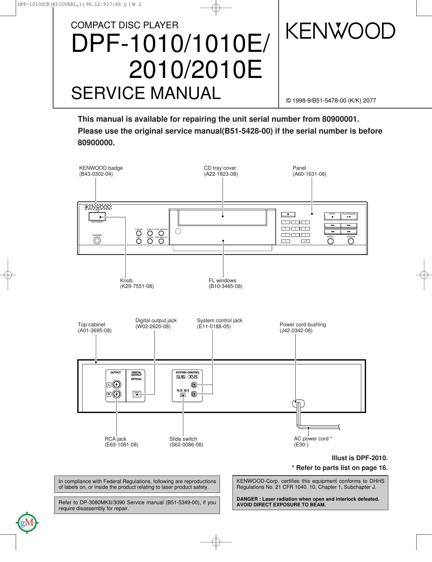
COMPACT DISC PLAYER

DPF-1010/101OE/ KENWOOD

201 0/201 OE
SERVICE MANUAL

This manual is available for repairing the unit serial number from 80900001.

Please use the original service manual(BS1-5428-00) if the serial number is before
80900000.

© 1998-9/851-5478-00 (K/K) 2077

KENWOOD badge CD tray cover

Panel
(843-0302-04) (A22-1823-08) (A60-1631-08)

|:I|:I|:I
SEMI. El

E
i:| lIl

\
K Knob FL windows
(K29-7551-08) (810-3485-08)
_ Digital output jack System control jack .
Top cabinet (W02-2620-08) (E1 1-0188-05) Power cord bushing
(A01 6695-08)

(J42-0342-08)

nlsirm.
nuwm
uvncAL

I:
a: :
RCA jack Slide switch AC power cord
(E83-1081-08) (862-0086-08) (E30-)

Illust is DPF-2010.
* Refer to parts list on page 16.

In compliance with Federal Regulations, following are reproductions

KENWOOD-Corp certifies this equipment conforms to DHHS
of labels on, or inside the product relating to laser product safety.

Regulations No. 21 CFR 1040. 10, Chapter 1, Subchapter J.

. . DAN EH : L ' ' h ' I k f .
Refer to DP-3080MKII/3090 SerVIce manual (351-5349-00), If you of: DIREacsTe'Eggsfiggngnag'm 3 '°' °° 9 we
require disassembly for repair. '

Page 2

J DPF7101OSCR(K)COVER1,1(98.12.917148 y [w 3
DPF-1010/1010E/2010/2010E

ACCESSORIES / CAUTIONS

%%

Accessories
,
Audio cord .................. (1) System control cord ...... (1)
(E30-2913-08) (E30-2912-08) AC plug adaptor .............. (1)
(EDS-011505)

(A70-1181-08) : RC-POSOS

Batteries (RB/AA) ........ (2) cord to the shape of the wall outlet.
(Accessory only for regions where
use is necessary.)
@Q
Flemote control unit ......... (1)

Use to adaptthe plug on the power

Battery cover : (A09-0356-08)

3
S
S

2
5
E

KENWOOD

+10

CDC)

EDIT

CDCDCDCD

TIME
DISPLAY

CDCbCDC)
QéQC)

[MODE

RANDOM
C)

REMOTE CONTROL UNIT
RGPDSOS

OUTPUT

Cautions

Nate related to transportation and movement

Before transporting or moving this unit, carry out the following
operations.

l Turn the power ON but do not load a drsc
2 Verrty that the drsplav shown appears

12345

E78510
Flat/1'55

11 12 1a 14 15
3 Wart a few seconds and set the unrt to STANDBY mode

1B 17 1E 13 ED

Operation to reset

The microcomputer may fall into malfunction (impossibil-
ity to operate, erroneous display, etc.) when the connec-
tion cords are unplugged while unit is ON or due to an
external factor. In this case, execute the following method
to reset the microcomputer and return it to normal condi-
tion.

Set the unit to STANDBY mode by pressing the ON]
STANDBY (I /(')) key, and after a few seconds, turn the
unitON by pressing the ONISTANDBV ll /L')l keyagain.

oPlease be aware that resetting the CD player wrll erase all stored
rnturrnatrun and return rt to the factory settings.

Page 10

pcosd2p98.12.9l/:4b y in 1 /\

DPL71 PWB
FM 7 I
_______________ I I I sw425 SW426 I
R425
_| -I- 65K -I-
I I REPEAT, A B, a é a I a I I 25 I CAUTION: For continued safety replace safety critical
'SINGLE TIME 1 3 4 5 . .
I I TRACK l I, I I, / I, I I sw423 MA I components only With manufacturers recommended parts
I I ITOTAI- TIME 6 7 3 9 10 I I -- 27 I (refer to parts list). A indicates safety critical components.
k c k 5 423 For continued protection against risk of fire replace only
_F.SEARCH
VD I 2 13 14 15 I I I with same type and rating fuse(s). To reduce the risk of
I sw421 R422 sw422 _ _
I l a l a I I 4- 15K __ I electric shock, leakage-current or resrstance
I 7 18 19 20 measurements shall be carried out (exposed parts are
I I I I - I acceptably insulated from the supply circuit) before the
I I I I_ CNS402 appliance is returned to the customer.
I I '_ _ _ _ _ _ _cfi402 I 2 The DC voltage is an actual reading measured with a high
a I impedance type voltmeter. The measurement value may
9 I - I vary depending on the measuring instruments used or on
I RMcMH I the product. Refer to the voltage dur ing PLAY unless
. D N I I I otherwise specified; The value shown in ( ) is the voltage
I éfizgqtrmnusm wowowgomogggg I I measuredatthemomentofSTOP.
_m,_x,os~sm mu. crws
I-IGIfiX'DG)@©.®®©®®®®©©®®®®®®®®®®©®F-Rw-DBF-I I I
330 .
I: lllIlIlIIIIIIIIIIIIIIIII W1 MI I
: «muamw-wogsssssgsgsgg; 45 , low/mi I
xx 1 7T 7 77777777 77777777 7777 {45 33/100 SBUSVI "we
a a a My é H335 X X .5v .5v I
van 330 D302 g g g % I snug: I
>-> m g, u a _
c: o § 2: g a a Q-IAV
9 D 8 U C' b @AB) I 28C2878B LC78620E
I . 1: @fi cy .
7 R5; 7 JKS 7 d 3" D \ a I \ '
390 I e a tr 3 2'
DIGITAL I
VDD VDD vuo R52 2 U} OUT I 8% ;r K I
a 9 44 Y
2 g; 3 o I I Q-HV I
' 1 @air 3 73-9 s 1
0 v I x @-u g I c109 nus 5 I \___.I_D_Fm6 1 ®
8 a W X W E: I I- - - - ONLY 96 Q I
R59 > I mm R105; Emua I as 53 @ I
max m EEK «5% I 79 ®
was? 3 mu7§ ému III? 66 ID I /\
531w . 47K0 V m I; § té WES m a % JKI 49 I
2% e e E9 5 g ze® I
g 0 0 ' 0101 0103 26 @
> 16 G)
N < 0102 0104 KEY!) ® I
3% g 5:: a: me me m o |
R 1 1K 1K 0 KEYZ Q I
5 R120 Rt22 R12A ,KEYS Q
g | | |
5 T gmrv I | |
£5 52 I
g; | I
| | |
43
42 D I I I
WISHW g m MI I POWER PWB
- 22 1201/ __ ________
:I INTERFACE rE may I _I
- ; A0201 AXRZI D210 (
I W501
Q 9 § g Ream 5V $51M I: I SIEVHON |
o a p a a , L 117v g: . I
S K S g % I s g "9 CNP201 CNPSOI I
-~)-o-( a X 751/ U»
a) Is m1): E E C} I
a m m s 2 ®
a > I- 3 ch501 © I
> a? K2201 ®
l é) a I
a av w
you)- ? 89¢?va § 5 m me 3 ® 0
:17 3&775831/ I N g g; c I
b-1 E a I
R2 20205 0 a - I 9 02147217 I IMI Acnotzflv
"1K? 0203Q g 3 § 82 3g C22746227 I ggdgaav»
a 7 a Na :7 2
g; ai § 3 M, I '2 03 US I I A22 J 1x: ACZAW 5on
08 S: 0 -av -E - 11H Aczauv 5qu
,3 _ N D212 I
8% 33 Ex GE 37% ' 95v
' " fl $2 5% R224 I
729 fig Rzu 0213 m I
§ 7290M o2o2A 3551/ 0203 I
a r I
EN 3 N I T I DPF-1 1 1 1 E 2 1 2 1 E
l I DPFr1010/2010(SRC)
nzv _I Y22-7980-50

/'\
\./