Kenwood DPF 2010 E Service Manual

This is the 14 pages manual for Kenwood DPF 2010 E Service Manual.
Read or download the pdf for free. If you want to contribute, please mail your pdfs to info@audioservicemanuals.com.

Page: 1 / 14
left right
Kenwood DPF 2010 E Service Manual

Extracted text from Kenwood DPF 2010 E Service Manual (Ocr-read)


Page 1

ppreloloscmx) COVERl,l(98t12.9l7:48 y [w 2 :r
K

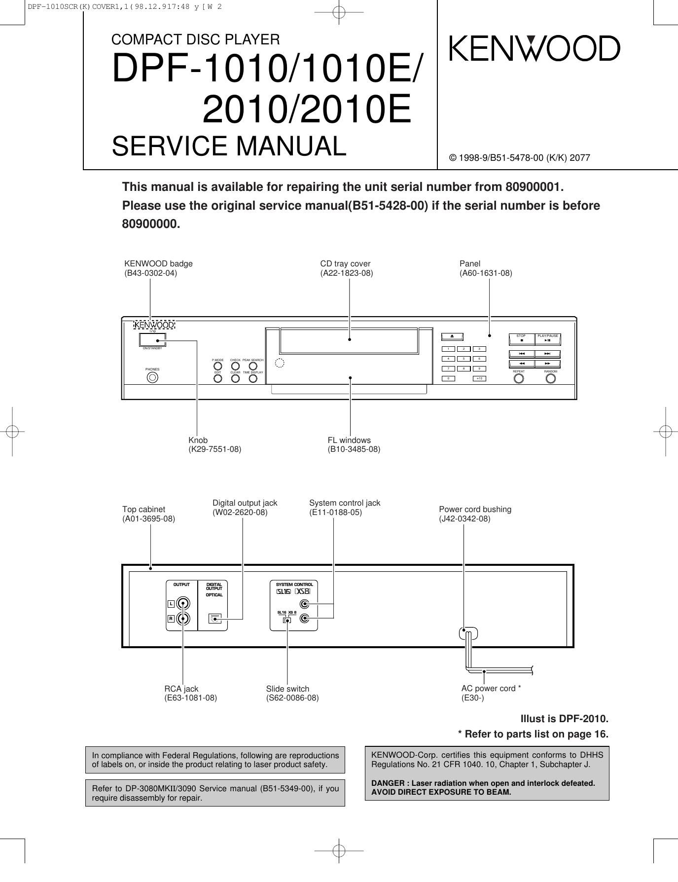
COMPACT DISC PLAYER

DPF-1010/101OE/ KENWOOD

201 0/201 OE
SERVICE MANUAL

This manual is available for repairing the unit serial number from 80900001.

Please use the original service manual(BS1-5428-00) if the serial number is before
80900000.

© 1998-9/851-5478-00 (K/K) 2077

KENWOOD badge CD tray cover

Panel
(843-0302-04) (A22-1823-08) (A60-1631-08)

|:I|:I|:I
SEMI. El

E
i:| lIl

\
K Knob FL windows
(K29-7551-08) (810-3485-08)
_ Digital output jack System control jack .
Top cabinet (W02-2620-08) (E1 1-0188-05) Power cord bushing
(A01 6695-08)

(J42-0342-08)

nlsinu.
nuwm
uvncAL

I:
a: :
RCA jack Slide switch AC power cord
(E83-1081-08) (862-0086-08) (E30-)

Illust is DPF-2010.
* Refer to parts list on page 16.

In compliance with Federal Regulations, following are reproductions

KENWOOD-Corp certifies this equipment conforms to DHHS
of labels on, or inside the product relating to laser product safety.

Regulations No. 21 CFR 1040. 10, Chapter 1, Subchapter J.

. . DAN EH : L ' ' h ' I k f .
Refer to DP-3080MKII/3090 SerVIce manual (351-5349-00), If you of: DIREacsTe'Eggsfiggngnag'm 3 '°' °° 9 we
require disassembly for repair. '

Page 2

J DPF7101OSCR(K)COVER1,1(98.12.917148 y [w 3
DPF-1010/1010E/2010/2010E

ACCESSORIES / CAUTIONS

%%

Accessories
,
Audio cord .................. (1) System control cord ...... (1)
(E30-2913-08) (E30-2912-08) AC plug adaptor .............. (1)
(EDS-011505)

(A70-1181-08) : RC-POSOS

Batteries (RB/AA) ........ (2) cord to the shape of the wall outlet.
(Accessory only for regions where
use is necessary.)
@Q
Flemote control unit ......... (1)

Use to adaptthe plug on the power

Battery cover : (A09-0356-08)

3
S
S

2
5
E

KENWOOD

+10

CDC)

EDIT

CDCDCDCD

TIME
DISPLAY

CDCbCDC)
QéQC)

[MODE

RANDOM
C)

REMOTE CONTROL UNIT
RGPDSOS

OUTPUT

Cautions

Nate related to transportation and movement

Before transporting or moving this unit, carry out the following
operations.

l Turn the power ON but do not load a drsc
2 Verrty that the drsplav shown appears

12345

E78510
Flat/1'55

11 12 1a 14 15
3 Wart a few seconds and set the unrt to STANDBY mode

1B 17 1E 13 ED

Operation to reset

The microcomputer may fall into malfunction (impossibil-
ity to operate, erroneous display, etc.) when the connec-
tion cords are unplugged while unit is ON or due to an
external factor. In this case, execute the following method
to reset the microcomputer and return it to normal condi-
tion.

Set the unit to STANDBY mode by pressing the ON]
STANDBY (I /(')) key, and after a few seconds, turn the
unitON by pressing the ONISTANDBV ll /L')l keyagain.

oPlease be aware that resetting the CD player wrll erase all stored
rnturrnatrun and return rt to the factory settings.

Page 6

J DPF*101OSCR(K)COVER1,1(98.12.917148 y [w 5 44%
DPF-l010/1010E/2010/2010E

ADJUSTMENT

CD section

Since this CD system incorporates the following automatic
adjustment function, when the pickup is replaced. it is not neces-
sary to readjust it

Since this CD unit does not need adjustment, the combination
of PWB and laser pickup unit is not restricted.

~Automatic adjustment item

1. Focus offset(Fig.1)

2. Tracking offset(Fig.2)

3. E/F balance (Tracking error balance) (Fig.3)

4. RF level AGC function (HF level :constant)

5. RF level automatic follow-up of the tracking gain

This automatic adjustment is performed each time a disc is
changed. Therefore. each disc is played back using the optimal

settings
0,1
0.5;V 200"}5
IC] FD tV/dIV
\ @ rm @m
x Focus
offset
adjulmem
0.15
0,50V $393;
I
lCl @YE Tracking Ict @TE
offset
adjustment
Fig.1
toms Enlarged
0.50V view
Ic1 @ro
10ms
asov T H
Ict T0 rac ng
@ offset
adjustment

T/E BALANCE
Pin 7 of lC-l

F/O
Pin 15 of (0-1

T/O
Pin 15 of IC-l

Tracking
error
balance
adjustment

Fig.2

Fig.4 Checking points