Kenwood DPCX 612 Service Manual

This is the 15 pages manual for Kenwood DPCX 612 Service Manual.
Read or download the pdf for free. If you want to contribute, please mail your pdfs to info@audioservicemanuals.com.

Page: 1 / 15
left right
Kenwood DPCX 612 Service Manual

Extracted text from Kenwood DPCX 612 Service Manual (Ocr-read)


Page 1

DPC7X311(K)INT1P 7/28/00 4:27 PM \°~/1 /\

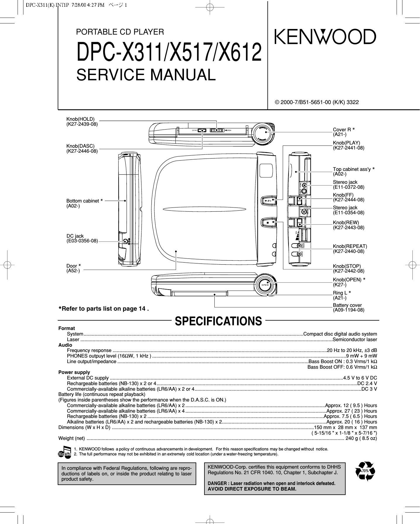
BREE-323A1YE1R/X517/X612 KENWOOD

SERVICE MANUAL

© 2000-7/B51-5651-00 (K/K) 3322

assuage) .
@' Mn Elflmw rm EDAOZVIe-SR *
§ W Knob(PLAY)

mtgygnggs) (K27-2441-08)

T06) cabinet ass'y *

Stereo jack
(E11-0372-08)

Knob(FF)
Bottom cabinet * 4' MIR (K27'2444'03)
(A0?) © Stereo Jack
(E11-O354-08)
- -- , Knob(REW)
(K27-2443-08)
DC Jack

(Eos-osse-os) 4.

Knob(REPEAT)
(K27-2440-08)

0 Door * 3 Knob(STOP)
(A52-) -(K27-2442-08)
fig \ Knob(OPEN) *
(Wm (K27-)
Ring L *
I ' (A21-)
. B t
*Refer to parts St on page 14 . ffiafigfifgg)
Format
System Compact disc digital audio system
Laser .. ................. Semiconductor laser
Audio

Frequency response" 20 Hz to 20 kHz, 13 dB
PHONES outpuyt level (169W 1 kHz) .......... 9 mW + 9 mW
Line output/impedance... ............................................................................................................................. Bass Boost ON : 0.3 Vrms/1 kQ

Bass Boost OFF: 0.6 Vrms/1 kQ

Power supply
External DC supply ...............................
Rechargeable batteries (NB-130) x 2 or 4
Commercially-available alkaline batteries (LR6/AA) x 2 or 4

Battery life (continuous repeat playback)

(Figures inside parentheses show the performance when the D.A.S.C. is ON.)
Commercially-available alkaline batteries (LR6/AA) x 2
Commercially-available alkaline batteries (LR6/AA) x 4
Rechargeable batteries (NB- 130) x 2
Alkaline batteries (LR6/AA) x 2 and re

Dimensions (W x H x D).. .

.5Vt06VDC


(5- 15/16 " X1- 1/8 " X5- 7/16 ")
Weight (net) ...... 2..40 g (8.5 oz)

1. KENWOOD lollows a policy of continuous advancements in development. For this reason specifications may be changed without notice.
@ 2. The lull perlormance may not be exhibited in an extremely cold location (underawater-freezing temperature).

In compliance with Federal Regulations, following are repro- KENWQOD'COYP- certifies this equipment COHfOfmS t0 DHHS 11%
ductions of labels on, or inside the product relating to laser Regulatlons NO 21 CF 1040- 10, Chapter 1, SubchapterJ. v.~
roductsafet t
p y DANGER : Laser radiation when open and interlock defeated.
AVOID DIRECT EXPOSURE TO BEAM.

l l J?

Page 4

r\
\J

DPC7X311(K)INT1P 7/28/00 4:27 PM \°-/ 4

/\
\/

DPC-X311/X517/X612

CIRCUIT DESCRIPTION

1. Microprocessor : MN101C439(ICS)
1-1 Pin description

Pin No. Pin Name IIO Description H Active L
1-4 COM 0-3 O LCD common output.
5 VLC3 - GND
6,7 VL02,1 - VDD
8 VDD - VDD
9 0802 - Unused.
10 SMCK | External system clock(4.2336MHz).
1 1 VSS - GND
12 X1 - GND
13 X0 - Unused.
14,15 MMODO - GND
16-18 ANO-2 - Unused.
19 KEYO | Remote control signal input.
20 KEY1 | Key signal input.
21 BATT. | Battery level detection port. LOW BATT
22 NC - Unused.
23 RECHARGE DET I Rechargeable detection port.
24 VREF+ - Power supply(+2.8v).
25 REM DATA 0 Remote control data output.
26 POWER 0 Power off control for CD servo driver. POWER OFF
27 REM STATUS - Unused.
28 P03 - Unused.
29 SUBQ | Sub code Q signal input port.
30 SQCK 0 Sub code clock output port.
31 P06 - Unused.
32 NRESET | Reset signal input for microprocessor.
33 XRESET 0 Reset output port to DSP |C(IC4). RESET
34 STAT | Status signal input port.
35 MLD 0 Command load signal output port of microprocessor.
36 MDATA 0 Command data signal output pon of microprocessor.
37 MCLK 0 Command clock signal output port of microprocessor.
38 BLKCK | Sub code clock signal input.
39 IRQ1 - Unused.
40 DOOR | Door switch detection input. OPEN
41 TEST - Unused.
Power voltage change-over
42 V CONT" O H = DC/DC out 3.0V L = DC/DC out 2.7V
43 BBS O Bass boost control output. BBS ON
44-46 P42-P44 - Unused.
47 LMT | Limit switch detection input port.
48,49 P46,P47 - Unused.
50 MUTE O Muting control port of audio signal. ON = H
51 LIGHT OUT - Unused.
52 RECHARGE I Detection port for rechargeable battery. BAT CHG ON
53-55 P53,P54.P60 - Unused.
56 AC ADAPTER | Detection port for AC adapter. BATTERY AC ADAP.
57 HOLD | Detection port for hold switch. HOLD ON
58 DASC | DASC switch detection port.
59 DASC1 - Unused.
60 DASC2 - Unused.
61 P66 - Unused.
62 DIG OUT - Unused.
63-68 SEG12-SEG17 - Unused.
63-80 SEGO-SEG11 O Segment control output.