Kenwood DP 860 Service Manual

This is the 48 pages manual for Kenwood DP 860 Service Manual.
Read or download the pdf for free. If you want to contribute, please mail your pdfs to info@audioservicemanuals.com.

Page: 1 / 48
left right
Kenwood DP 860 Service Manual

Extracted text from Kenwood DP 860 Service Manual (Ocr-read)


Page 1

CO Piééo KENWOOD

SERVICE MANUAL

1987-3 PRINTED IN JAPAN
B51<3168

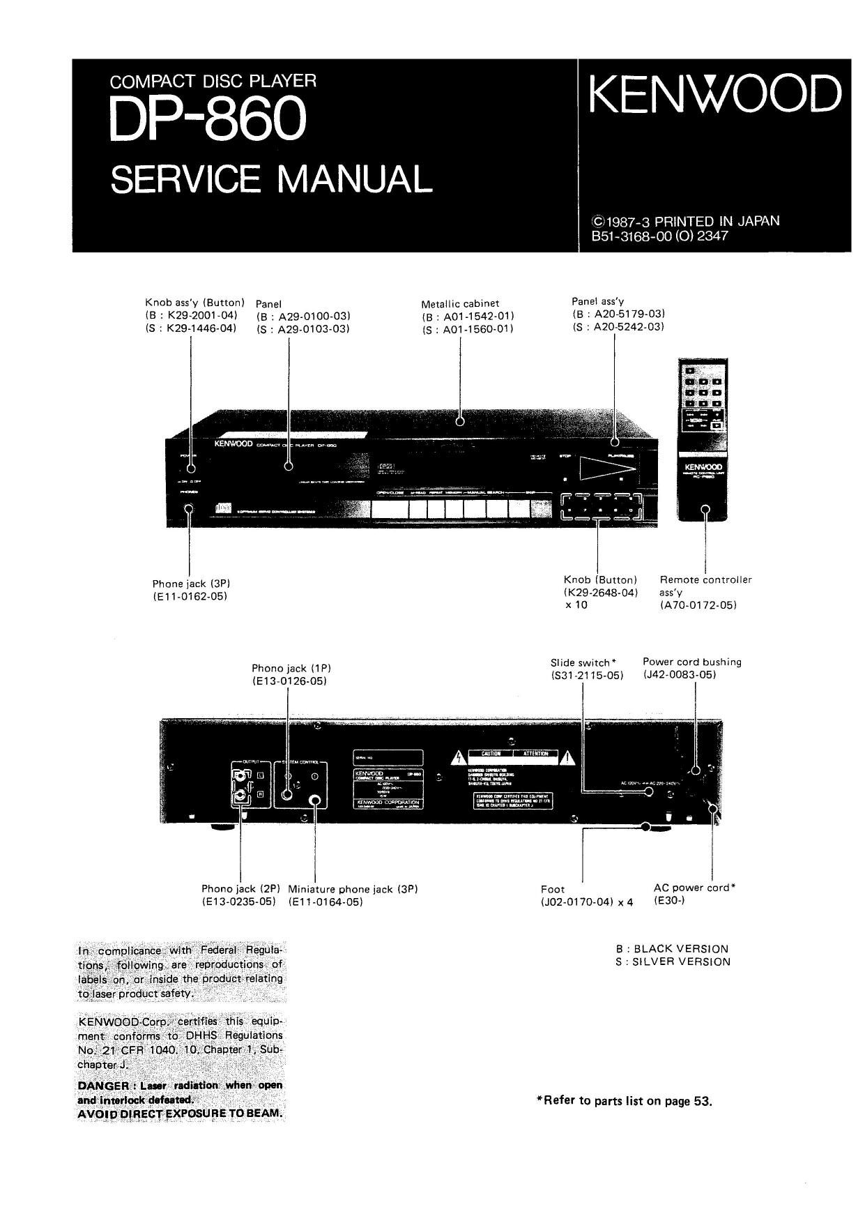
KIWI 35 mum) Panel MetalIic cabinet PaneI aSS'V
(B = K29-2001A04) (B : A29-0100-03) (B : Ao1-1542~o1) (B : A20-5179-03)
I5 1 094445-04) Is : A29»0103-O3I (s : A01»1560»01> (s : A20-5242-03I

KENWOOD {1-44th 1

Phone jack 13F) Knob (Button) Remote controller
(E110162-05I IK29-2648»04I ass'v
x10 (A70»0172-05)
phom jack up) Shde swctch Power cord bushing

(93.012505) I53172115-05I (J42v0083-05)

Phono jack I2P) Miniature phone jack I3PI Foo: AC power cord
(5130235435) (E1 I 43154-05) (J02-0170-O4I X 4 (£300

B 3 BLACK VERSION
S SILVER VERSION

*Refer to parts list on page 53.

Page 2

CONTENTS/TRANSPU RTATION SCREW

TRANSPORTATION SCREW .................. 2
CONTROLS AND INDICATORS ............... 3
DISASSEMBLY FOR REPAIR ................. 4
BLOCK DIAGRAM ........................ 7

CIRCUIT DESCRIPTION
1. General description of microprocessor

operation ........................... 8

1»~i. General description of operation ........ 3

0 Test mode ..................... 8

0 Normal mode ................... 8

1-2. Key Description ....... 9

0 Normal mode ................... 9

I Test mode display ............... 1D

2. Microprocessor : uPD752060W-023 (X25-2920-XX :

|C5l .............................. 13

2-1. Terminal connection diagram ......... 13

2~2t Terminal Description ............... 13

2-3 Flow chart of test mode ............. 14
0 Flow chart form tray OPEN status after

power ON .................... 14

0 Focus search & Focus servo ON ...... 15

0 Tracking servo ON .............. 16

0 Disc motor stop ................ 16

0 From loading of 0 data to display , , . . 17

241, In a usual case, since the tray was pushed when
the tray is OPEN until STOP display is

made ......................... 17
3. RF Amplifier : CXA1081S (X25-2920-XX :
IC1) .............................. 18
3-i, Functions ...................... 18
3~-2. Terminal connection diagram ......... 18
3-3. Block diagram ................... 18
3-4, Explanation of functions of components . . 19
3- DEFECT Circuit .................. 20
4. Servo signal processor : CXA1082$ (X25-2920-XX :
I62) .............................. 21
4-1. Functions ...................... 21
4-2. Terminal connection diagram ......... 21

Transportation screw

Before operation, remove the two red screws attached to the
bottom of the unit used during transport from the factory.
Remove both screws using a coin] etc. and, after removing,
retain them together with the Warranty card and other
documents When the unit is to be transported again, be sure
replace the two screws to their original position:

4-3. Block diagram ................... 21
4-4. Explanation of terminals ............ 22
5. Digital signal processor : CXD11300 (X25-2920-XX :
lC3) .............................. 23
6-1. Functions ...................... 23
5-2. New auto servo .................. 23
5-3. Terminal connection diagram ......... 23
5-4, Block diagram ................... 23
5-5. Explanation of terminals ............ 24
6. D/A converter : PCM56P (X25-2920-XX :
IC'I) .............................. 25
671. Block diagram/Terminal connection ..... 25
6-2. Explanation of terminals ............ 25

7. Description of components
7-1. ELECTRIC UNIT (X25-2920-OO,-21l ... 26

MECHANISM OPERATION DESCRIPTION ....... 27

1. OPEN/CLOSE operation ................ 27

2. Disassembling procedure of mechanism section . 30

2-1, Removing the clamper arm ........... 30

2-2. Attaching the clamper arm ........... 31

2-3. Removing the tray ................ 31

274. Attaching the tray ................ 32

2-5. Removing the slider ass'y ............ 32

2-6, Attaching the slider assv ............ 33

277 When movmg the pickup forcibly ...... 34
ADJUSTMENT

ADJUSTMENT ........................ 35

REGLAGE ........................... 37

ABGLEICH ........................... 39

DIFFRACTION GRID ADJUSTMENT ......... 41

VOLTAGE CHECK TABLE ................ 42

PC BOARD (COMPONENT SIDE VIEW) ......... 43

PC BOARD (FOIL SIDE VIEW) ............... 45

CIRCUIT DIAGRAM ...................... 47

EXPLODED VIEW (MECHANISM) ............. 51

EXPLODED VIEW (UNIT) .................. 52

PARTS LIST ............................ 53

SPECIFICATIONS ................ BACK COVER

Page 11

CIRCUIT DESCRIPTION

Input kev E Function Display i Remarks
REPEAT Used to check the power of the laser diode. TRACK N0 dLasgr
(MODE : Tray OPEN and Lo (laser diode) 0N. i 0 9
02 (MANUAL SEARCH, SKIP, MEMORY, MEEAD, PLAVAPAUSE i Ll_l -/ I ESQ?

and numeric keys (0N9) are invaiid.) I__/ I: 1
1 STOP key .......... LD OFF with tray opened.
Note : Special memory operation : in the 02 mode above, when the TRACKVNO
OPEN/CLOSE key is pressed with the STOP key ON,a special (/7
; memory operation is entered, (Tray is ieft opened.) L
When the OPEN/CLOSE key is pressed again, the tray will close and
track no.2,6,718,10 and 13 will be entered into memory. (with
SONY Test Disc Type 4) i t 'nAc< no y,- TiME
i ' i i
1With this condition, pressing the PLAVAPAUSE key will play the > L__ _ 5
above tunes in the other above I I _/
OPEN/CLOSE .......... Normal mode resumes. } I, l- _
M-READ i Focus ON (tracking, feed OFF) ? PAUSE WW :Tracking
(MODE 03) 3 When focus is OFF, performs in the following order. ierror
Focus search -> Focus ON -> Disc motor ON -> CLV ON LII-I :/ iadyustment
In MODE 03, Operation and dispiay when the ipiiowing key is i may F-TiAC-K'idj
pressedt i > /
i ~ PLAV key .......... PLAY Ll_ll:
:l 1_/ _l i
. SKIP H4 key or av ]r TRACK mo 1
MEMORY key Tracking ON 3 I
Li*/ I_/
i l_/ I
muss rrmcx No
M»READ key t ...... No change ll / i
i . REPEAT Invalid LI-I _l
1 - Numeric keys ......... Invalid LI 3
i TPVACK NU
When display appears by pressing the MANUAL SEARCH key » /-
or « ,pressing the STOP key resumes MODE 01, i L/-/ /
I_I I
MEMORY Focus, tracking ON (Feed OFF)
(MODE 04)

When focus is OFF, performed in the following order 1

Focus search -> Focus ON % Disc motor ON -> CLV ON

a Tracking ON
Operation and dispiay when the following key is pressed in MODE 03.
i- PLAY key or SKlPMkey. , _PLAV

- M-HEAD key or

SKIP H4 key ........ MODE O3

- MEMORV key ........ No change
i - REPEAT key ......... Invalid
- Numeric key ......... Invalid

When display appears by pressing the MANUAL SEARCH key »
or « ,pressing the STOP key resumes MODE Olt

PLAY YRACK NO
[
I_l I_l
Ll I

PLAY TRACK NOA
> i
LII I:
L! _/

PAUSE TRACK No

I l __J
I_/_I

PLAV TRACKNO,

> [
I_I/_l
l_/ I

TRACK NOV

l/
/_I/

11

Page 27

DP-86O

MECHANISM OPERATION DESCRIPTION

Mechanism operation description

Fig. 1 shows the mechanism positioning in the STOP
mode. The OPEN/CLOSE operation when loading the
disc is described below.

Note :

In the operation description, the black and white arrows
shows the following code :

Black arrow : Shows the opening direction of the tray
(Tray OPEN).

White arrow : Shows the closing direction of the tray
(Trav CLOSE).

Also in the operation description and illustrations,
numbers in brackets ( l followed by the part name
show the identifying numbers of the disassembly diagram
in the Service Manual.

Disc motor ass'vi45) Lifter arm 19)

Tray ass'v
tension coil
spring (25)

Main gearl12)

Geerl13)

Belt(17l

Loading DC
motorl43)

Slider ass'vl11)
OPEN/CLOSE

detection leaf
switchlS1)

Slider tension coil springi22)

ChassislBOi)

1. OPEN/CLOSE operation

The center of the OPEN/CLOSE lug detection leaf
switch installed on the PC board (J25A5506-02iA/3H
on the rear of the mechanism is pressed to the right by
lower side of the tip of the black switch arm (6) installed
on the slider ass'y (11) when the tray is closed. and the
information is transferred to the microprocessor. This
status is called the tray CLOSE operation. The operation
from this status to the condition when the tray is comple-
tely opened by pressing the OPEN/CLOSE key is described,

Tray134)

Laser
pickupi32)

Clamper arm (8)

Fig. 1 Tray closed status