Kenwood DP 850 Service Manual

This is the 24 pages manual for Kenwood DP 850 Service Manual.
Read or download the pdf for free. If you want to contribute, please mail your pdfs to info@audioservicemanuals.com.

Page: 1 / 24
left right
Kenwood DP 850 Service Manual

Extracted text from Kenwood DP 850 Service Manual (Ocr-read)


Page 1

COMET-DggwoER ' \V 2 KENWOOD

TRio-KENvi/OOD CORPORATION

SERVICE MANUAL ., i

i

©1b86-4 PRINTED IN JAPAN
1954-OO(O) 2338

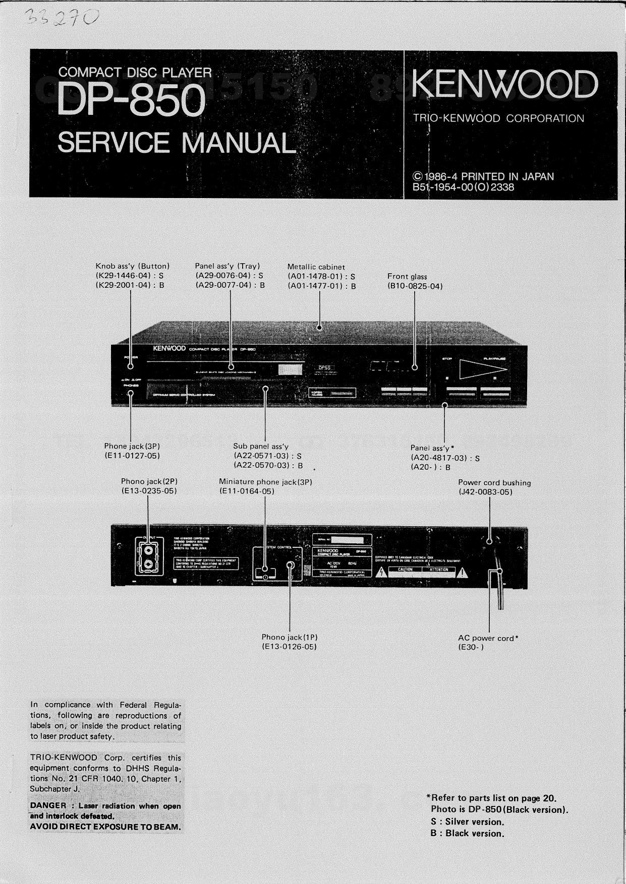
Knob ass'y (Burton) Panel assy (Tray) Metailic cabinet
(K294411604) : S (A29»0076-04J : S (A01-1473-01) : S Front glass
(K29-2001-04) 1 B (A29~0077-04) : E (A014477-01) : B (310-0825-04)

Phone iack(3P)

Sub panel assy Panel ass'y'
(E1 1 {1127-05)

(A22-0571-03i : S (A20<4817-03) : S
(A22-0570-03) : B (AZO- ): B

Phono jack(2P) Miniature phone jack(3P) Power cord bushing
(E13-0235-05) (EH-016405) (NZ-008305)


on...
"mu a...

amunluumvmml
Enuflvrxw-u m u. .

Phone jack P) AC power cord
(930126-05) (E30-)

In complicancer with Federa| Regula~
tions, following are reproductions of
iabeis qn, or inside the product relating
1o laser product safety.

TRIO-KENWOOD Corp, Certifies this
equipment conforms to DHHS Regula-
Iions No 21CFR 1040 10 Chapteri,

Subcham J

Refer to pans list on page 20.
DANGER Lunr radiatxgn whon open Photo is DP-850(Black version).
and "5de WM- ' S : Silver version.
AVOID bmscr EXPOSURE TOBEAM. B . Black version

Page 2

DISASSEMBLY F OR BEPAI R

REMOVING THE FRONT PANEL

1. Turn the power oil with the disc tray opened then
vemove the top cover.

2. Lin up the disc clamper in the direction of arrow 0 .
Then pull out the disc tray tmrd you while holding
the tray stopper grips inside ( o l.

3, Remove the three screws ( 91- Pull out the lower side
oi the front panel tuward you (0 l. Now, the trout
panel is tree from the grips cf the seepenel.

REMOVING THE PICKUP

4. Remove the disc tray] and the four screws (9) re-
taining the meChanlsm ass'y (X92-1120-01).

5

DISASSEMBLY FOR REPAIR

, Turn the mechanism assy (X92-1120-01) over (9 l.

and remove the tvvo rod shaft retaining screws l 0 l to
remove the rod shatt and plckup (em-028045) (9).

Remove the three screws (9) retaining the pickup
(.1910280-1 5) and metal lilting.

. Unsolder the LD pin of the pickup (JEN-028015) ( @l.

Unsoldar the ALPC PC board and relay PC board (X29-
17oooo 8/2) (0 i.

when remnvilll thl nhy PC board, uw the not what
(outer luck" of the shielded win, etc.) dipped in flux
fat maniom.

. When installing the new pickup (J91-0280-15) for re-

placement, fully turn the trimming pot, (VH1) on the
ALPC PC board (XE-170000, A/Z) counterclock-

wise. i Q l

Thlt I! to prevent the our Incl from outputting.

Note:

Whln handling Eh. pickup BI-028045) directly with
you: hind. be sure to disch-m any tutic cumin hui|-
up II I puvantlu manure. [Operation table, body and
soldering iron, ell.) Luv. the later diode ILDI short pln
attached u long it unniblu or until lmlmdittely befm
operation.

Unluu the about it purformed, the life of the lam diode
might be shortened, or may noon become defective.

Page 8

r P-850

CIHCUIT DESCRIPTION

Function of supplement (ICE)

a) Bit dock reproduction by EFM-PLL circuit

The EFM signal read out from the optical pick-up con»
tairls a 2,15MHZ clock component, so the EFM'PLLCHCUH
an extract a 4.32MH2 bit clock (PLCK) which is in sync.
with this clock.

At every edge of the EFM signal, the phase inversion
with the PLCK, which is 1/2 VCO, is performed, and out-
put is TRIVSTATE from PDO pin. When in sync. the PDO
pin average value is about l/2~VDD. But when VCO is
higher, the average value drops, and increases when it is
lower.

h) EFM DImodul-tion

14 bit data is extracted from the 23 bit shift register
and demodulated to 8 bit data through the 14 to a con-
version circuit composed of a logic array. After this. a
writerin request (WREQ signal) is ourpui to the RAM
interface block, and the data is output to the RAM data bus
(DBOB~DBOl pins),

c) thcnde demodulation

The 14 bit subcode sync. signals 50 and 51, irom the
23 bit shilt register, are detected and sampled at timing
synchronized to WFCK, Alter delaying so one frame,
80 + 51 (093(1) is output from SCOR pin, and SO, 81
are output from $880 pin (only when SCOH 5 "H".}

After .the subcode data (P-W) is EFM demodulated,
the data is inpur to the register at timing synchronized to
WFCK, and subcode Q is output lrom SUBQ pin. Then,
subcode data (P-Wl is loaded to the 8 bit shift register,
and output from $350 pin according to the EXCK pin
clock.

11) Subcodn 0 error detection

Subcode 0 CRC (cyclic redundancy check) results are
output from CRCF pin in sync. with SCOH pin. when
error is detected, CRCF oin output goes low.

ll Jitur Margin

EFM demodulated data is synchrnonized with PLL
in data playback section. There'ore, it includes disc rota-
tion servo, etc. disturbances (wow, flutter. etc.l. This data
is written into the external RAM. The data read from the
RAM is synchrronized to the clock from X'tal, so this
means that the RAM is doing time axis correction,

However, the limits of time axis correction are deter-
mined by RAM mortally. On this system. when read/write
lrames are :5 frames apart, other data is destroyed. Under
those conditions. the playback sound cannot be guaranteed
There is a base counter monitor to avoid this problem.

In other words, when READ/WRITE base counter dif-
ierehce goes over 14 frames. the HEAD base counter value
is set in the WRITE base counter. The result is that none
corrected error data in the RAM is not output to D/A
section.

The RAOV signal outputs "H" for 1 frame lWFCK)
interval when the base counter alilcrerrce goes over :4
frames,

t) Error monitor

When PSSL pin is made low, signals which can monitor
error correction are output. There are C1F1. Cl F2, C2F1
and C2F2, output to DAOINDAOII for min. 472715 alter
RFCK tailing edge. The levels and meanings or these signals
are shown below.

Cl Fl Cl F2 Cl correction state
0 o No error
l 0 I error Correction
0 l Double error Correction
I l Correction not enabled
CzF l cze C2F L C2 correction state
0 0 0 No error
i 0 O I error Correction
0 'l 0 Double error correction
l l 1 Correction not enabled.

CXZO152 87)

Block dilylm ll 07)

DP-850

CIRCUIT DESCRIPTION

4

Mse counter

constant
current

source

LSB counter

1L1. logic levll ulnv
TIMING GENERATOR
5N" reslstor, Larch

Explanation of terminal: (IC7l

Tomlin-I No. Mans. I/o Exgl-n-tlon

i DVEE - Nautilus Dower supply to digital system.

2 sue - sue STATE. common voltage with DVEE.

3 scLK Not used.

4 Vol: - Pcwsr supply.

5 ore/oer: Not mad

6 LATCH l Synchronous signnl incut rcr deglircher control.

7 LfiCK l UPI en separation signal incur, "L"; Rch, H" ; Lch

a WCLK | Word clock input tram digital signal processor, leazxriz)
9 BCLK l Ell clock innut trom digital signal Drocessnr. iczlo,2,lsMHzl
1D DIN l serial data ingur lrom digital signal processor. Input tram MSB.
ll LFlCK our 0 Deglllchercantrol slwsl.

l2 cc I D/A convenlon command input. Active "L

is DGND - Digital system GND.

l4 DVEE - Negatlve power supply to digital system.

15 OCH 0 Discharge control signal rc Rch integrator.

is |SET - Eils current swing or constant current source.

i7 IOUTR | Rch. constant current source output.

18 IOUTL I Lch, constant current source oulpul

is NC
20 AVEE _ I Negative nowsrsuppiy to Analog system.
21 AGND - Small signal analog system GND.

7.2 DGND - Digital system GND.

23 DCL 0 Discharge control signal to Lch integreror.

24 Dc ElAS - alas input to discharge control output,

25 COUT O Clock bufler out.

26 CIN | Clock cuiier non-inverted incur.

27 W l {Black curler inverted input.

28 DGND _ lurgnai sysuvn GND.

13