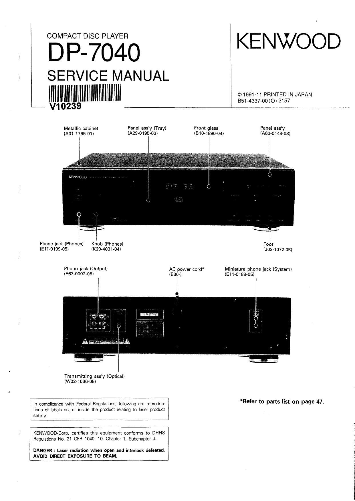
Kenwood DP 7040 Service Manual

This is the 42 pages manual for Kenwood DP 7040 Service Manual.
Read or download the pdf for free. If you want to contribute, please mail your pdfs to info@audioservicemanuals.com.

Page: 1 / 42
left right
Kenwood DP 7040 Service Manual

Extracted text from Kenwood DP 7040 Service Manual (Ocr-read)


Page 1

Digf'sfajo KENWOOD

SERVICE MANUAL

iiiiiiiiiiiiiiiiii iiiiiifiim

Metallic cabinet Panel ass'y (Tray) Front giass Pane! assy
(AO1-1755-D1) (A29-0195-03) (81 04 850-04) (A600144-03)

Phone jack (Phones) Knob (Phones) Foot

(EH-0199435) (K294103104) (J02-1072~05)
Phone jack (Output) AC power cord* Miniature phone jack (System)
(E63-0002-05) (E30-i (E11-0158~05)

Transmitting assy (Optics!)
(W02-1036-05)

*Refer to parts list on page 47.

in compiicance with Federal Regulations. following are reproduc~
tions of iabeis on, or inside the product reiating to iaser product
safety.

KENWOOD Regulations No, 21 CFR 1040. 10, Chapter 1, Subchamer Ji

DANGER : Laser radiation when open and interlock defeated.
AVOiD DIRECT EXPOSURE TO BEAM.

Page 2

DP-7040

CONTENTS/ACCESSORIES

CONTENTS
ACCESSORIES
CONTROLS ......
REMOTE CONTROL ..........
DISASSEMBLY FOR REPAIR ..
BLOCK DIAGRAM ....................
CIRCUIT DESCRIPTION
1. Test Mode ........................................................... 10
2. Microprocessor
: pPD75216ACW-C65 "0102) ...........
3. RF Amplifier : CXA1571S ((0104)
4. Servo Signal Processor
: CXAI37ZO (K3105) .......................................... 16

..... 12
..... 15

ACCESSORIES

- Remote control unit ........................... 1

(AN-056605) (E30 0505-05)

' Audio cord ............

5. Digital Signal Processor
: CXDZSOOAO (I09) .....................
6. Digital Filter : SM584OCP (IC7)
7. D/A Converter : CXDZSSZQ (I66)
MECHANISM OPERATION DESCRIPTION

ADJUSTMENT .............................................
PC BOARD (COMPONENT SIDE VIEW) ..

SCHEMATIC DIAGRAM ...................
EXPLODED VIEW (MECHANISM)
EXPLODED VIEW (UNIT)
PARTS LIST ........
SPECIFICATIONS

............................... 1

' System control cord
(E30-0977-05)


..BACK COVER

' AC plug adaptor .................................. 1 - Batteries ............................................... 2
(503-0115-05) H
4
a @153
(Except for some areas.)
For the unit with European AC plug in
areas other than Europe.
Note related to transportation and movement
Before transporting or moving this unit, carry out the following operations.
1. Turn the power ON but do not load a disc. __"*"__ w... m ,_
2. Wait a few seconds and verify that the display shown appears. 1 n I-l l-I. n n
(.1 1.! u U 14- I_' 1.:

3. Turn the power OFF.

Page 11

CIRCUIT DESCRIPTION

1-2. Key and functions valid in test mode

DP-704O

No. Input key Function Track No. display
1 PLAY) PAUSE (1) Focusing servo TRACK NO.
(D/II) (2) Tracking servo . I! 5'
(3) Feed servo Ll
J,
Displayed for a few seconds after
completion (1). (2) and (3),
J,
Time 5 (green Play mark),
and Disc Track No. are displayed.
2 DISPLAY (1) Focusing servo TRACK NO.
MODE (2) Trackin] servo. I7 :I
(3) Feed serv0.. LI -l
p (orange)
3 STOP (1) Focusing servo TRACK NO.
I I I (2) Tracking servo. I_I I
(3) Feed servo... (J I
4 UP Turns all FL display lamps ON. TRACK N0.
1 Ȣ ' "
) bl (1:;
5 DOWN Tums all FL display lamps OFF. "TRACK NO. is lighted. TRACK NO.
( i« ) fl I3
0 (=17
6 OPEN / CLOSE When the tray is opened then closed in rest mode. TRACK NO.
l A ) Track No. 7 and 8 are programmed and set is in STOP mode, 1] I7
The res! mode is canceled. I-I L,
7 FF In the STOP mode. moves the pickup toward the outer position of disc. TRACK NO.
( » ) The test mode is available at this condition. [-1 :1
U L
8 F8 in the STOP mode. moves the pickup toward the inner position of disc. -
I « ) If turn on stem limit switch, the pickup stops (0 move.

11