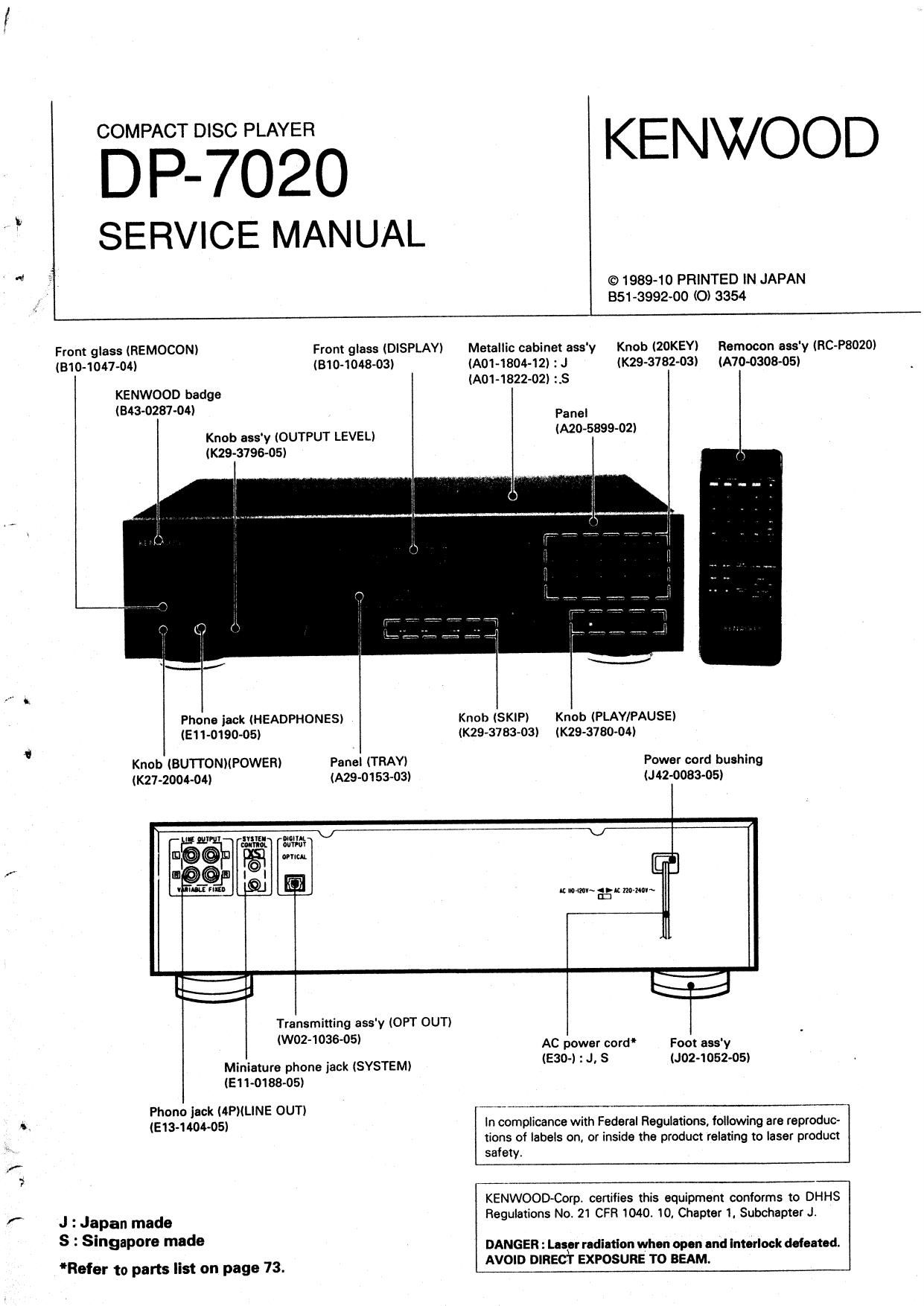
Kenwood DP 7020 Service Manual

This is the 45 pages manual for Kenwood DP 7020 Service Manual.
Read or download the pdf for free. If you want to contribute, please mail your pdfs to info@audioservicemanuals.com.

Page: 1 / 45
left right
Kenwood DP 7020 Service Manual

Extracted text from Kenwood DP 7020 Service Manual (Ocr-read)


Page 1

DP7020 K:NWOOD

SERVICE MANUAL

'1 7 © 1989-10 PRINTED IN JAPAN
351-3992-00 (O) 3354

1!

Front glass (REMOCONI From glass (DISPLAY) Metallic cabinet assy Knob (ZOKEYI Remocon assy (RC-P8020)
(310-1047-04) (810-1048-03) (AO1-1804-12) : J (K29-3782-03) (A70-0308-05)
(Am-182202) 2.5

KENWOOD badge
(343-0237-04)


Pa nel
(MO-589902)

Knob ess'y (OUTPUT LEVEL)
(K29-3796-05)

Knob (SKIP) Knob (PLAY/PAUSE)
(K29-3783-03) (K29-3780-04)

Phone jack (HEADPHONES)
(E11-0190-05)

,
Knob (BUTTONNPOWEFI) Panel (TRAY) Power cord bushing
(K21-2004-04) (A29-0153-03) (J42-0083-05)
mum
0k Wm"
t.
/
r-1
Transmining assv (OPT OUT)
(VI/02403605) AC power cerd Foot assy
Miniaiure phone iack (SYSTEM) I530" J' S J°2°52'°5
(E11-0188-05)
Phono jack (4PIiLINE OUTI
o. (513.1 404.05) In complicance with Federal Regulations, foliowing are reproduc-
tions of labels on, or inside the product relafing to laser product
safety.
A,
?
KENWOODCorpr cenifies this equipment conforms to DHHS
f. J : Japan made Reguiations No. 21 CFR 1040 10, Chapter 1. Subchapxer J.
s 2 SingaP°r° made DANGER : neerradi-flon when op." and imarlock donated.
*Refer to parts list on page 73_ AVOID DIRECT EXPOSURE TO BEAM.

Page 2

DP-7020

CONTENTS

CONTROLS AND INDICATORS
DISASSEMBLV FOR REPAIR
1. How to remove operation/mechanism ......... 4
2. Removing the tray .
3. Installing the tray
3. Removing the pickup (Japan made) .
3. Removing the pickup (singapore made) .
BLOCK DIAGRAM
CIRCUIT DESCRIPTION
1. Description of components
2. Display unit and u-com unit .
3. Sat mode flowchart
4.
5.


Test mode.
Microprocessor )1 75216
(X25-3820-00 : |C1l
6. RF AMP CXA1081§
(X32-1500-11 : ICIO4) ..
7. Servo control CXA12MS
(X3Z-1500-11 : IC103)
8. Digital signal processor LSI CXD11650
IX32-1500»11 : ICIl).... ...28

9. 18bit serial input DIA converter PCM1701
(X32-1500-11 : I06, 7) ..31
10. 8x oversampling di ital filter 8M5818AP
(X32-1500~11 : ICE)
11. D.P.A.C IC KAGM (X32450 11 .
MECHANISM OPERATION DESCRIPTION
1. Troy OPEN/CLOSE operation
2. Pickup chassis UPIDOWN movement
3. Gear instal ng position .
ADJUSTMENT
VOLTAGE TABLE
PC BOARD (COMPONENT SIDE VIEW)
PC BOARD (FOIL SIDE VIEW)
SCHEMATIC DIAGRAM...
EXPLODED VIEW (MECHANISM)
: JAPAN MADE .....
EXPLODED WEW (MECHANISM)
: SINGAPORE MADE
EXPLODED VIEW (UNIT)
PARTS LIST .....
SPECIFICATIONS...

BACK COVER

DIP-7020 JAPAN MADE SINGAPORE MADE
CONTROL UNiT' X324510-ll (K, P) X32-1562-71 (T. E)
X32-1510»21 (U. UE. M) 2456010 (K)
24512-71 (X)
MECHANISM ASS'V xsz-tamoz xsz-Moo-oz
[CDMer (CUM-145A)
Caution :

The mechanism ass'y used with the DP-7020 varies in two
types depending on the manufacturing location. (Japan, Sin-

gapore)

Belora Operation

I Transportltiou rcrrw

Baiore operation, remove the redrheaded screw attached
to the bottom of the unit used during transportation lrom
the tactory Remove the screw using a coin or screwdriver
etc
0 After removmg. retain the screw together with the
Warranty card and other documents,
0 When the unit is to be transported again, be sure to
replace the screw to its original position

1. Turn ON the power swrtch when no disc Is loaded
2 Watt a law seconds until the disc OUT indicator comes
"ON", Then turn "OFF" the power

3 Firmly tighten the transportation screw

DP-7020

CONTROLS AND INDICATORS

Program chock

Ploy mod. indicators ._\ indie-tor (P.C.) Time count-r
TRACK mode SINGLE TIME
PROGRAM mod. Truck numbor TOTAL TIME
TIME mode indicator

(TRACK N0.)

7 EMPHASIS indie-tor
{ IEMPHASIS)

RANDOM indicator
follssté;ndicator_4:iffii_l T o: :: (RANDOM)
3:21:11 indicator-"4- 4% L - Li . _: ET? lSSILAAiEErdIoator
L EDIT indicator
CCRS Indicator 4 (EDIT)

Index number indicator (INDEX)

Program number indicator (P No.)

Numeric keys (3 ~ 20/0

Display For deslanatmg blue. .Ind I ok numhsrs
REMOTE SENSOR , d m. Ind-calm: or all oi the
wln ow DISPLAV OFF key 5:. (mm the music calen-
OUTPUT LEVEL control
Disc trey REPEAT
l key

- , T
| i
. Search koys [EL » PLAY/PAUSE key [D]
PHONES lick um m Mama w (m. Us-a to switch alternately
revovlo the disc playing has. between on play «was
lion. and panic mod-
POWER switch Skip kays El (E) i E Play/Dense

Ussa to sklp Io sucnauIve indicator (M
k

°' "°"'°" m OPEN/CLOSE key (1] ,___ STOP key (E

Used to oven and close the

disc IraY

DISPLAY OFF key
it the DISPLAV OFF key is pressed during dlsc play, the
dlspley IS extinguished.

- it the DISPLAY OFF key is pressed at any time other

oWhen the disptsy is in the DISPLAY or; state
durlng program play, the display appears tor ap~
prOXImately 2 seconds at the beginning of each |

than durlng disc play, the dlsplay will not be extin- tune.
gmshed. The DISPLAY OFF slate is canceled when the DlSPLAY
- thhshoperatron key is pressed (excluding schist. or; key is pressed again or when the OPEN/

ment at the OUTPUT LEVEL control) while the
display is in the DISPLAY OFF state, the display
appears (or a law secands

CLOSE key or STOP key [:1 is pressed

Page 19

DP-7020

CIRCUIT DESCRIPTION

- Data and 0A0 control signal output (DOL, DOR.
BCKO, WCKO, DG, (YE. CWTQDWZO)

1) Output data format

1) MSB first

3] Output timing
The outputtiming of the audio output section is deter~
mined according to each internal system clock pulse

frequency.
2) 25 complement/COB (Complemented Offset Binary)
selection (CO-Bl ,, 5 mm in
2s complemejtlormat (COB:"H") "em Jaw,
COB format (COB=" Li mm mm
2) Qutput data number-ofbits selection duck pulse "fluency 92 256
(OI/V173. OWZOI an clock pulse penod Tb Tsvs ' Tsys
As to the number of bits for the outputdata, any of 16, Dam W01d|englh Tw Z4'Tsys aZTsvs
18 and 20bit can be selected,

Tsys internaI clock pulse period (Refer to Table 10-1 1
Tu Tw V serial output tinwig lReIer to Figure 13 I


iG-bit output (6W1
i8-bit output [6W .
20in output [5W1".H OWZO "L) bl. 10-2 output timing
However, this unit is set at the iarbit output mode.
l word OulDuX Period I
Tw

i r
It hurt I 20-" bits H-
i i

iwsnlrlillslelwl - iMIMILs ii E

I mm mm I
I

Wj WELL

i
I I-7w12-oI rs p-
l
I
I
|
l

,
i

Note n means the number oi antput word bits.

Fig. 13 Output timing

- System reset (El TI

When the reset input is made in the yitter~free mode,
the internal operation timing is reset in synchronization
With the leading edge of input LRCI, Making use of this,
the output timing in the jitterrfree mode can be aligned j

with input LRCIi
in the compulsory sync made, no sysrem reset is
needed Even in theiitter-iree mode. the output timing V55'

V00

V552 1

SMSBIJAP

does not need to be aligned With input mill and no
system reset is necessary

For system reset at power ONiexternaliv connect a 51
capacity or around 100pF ro pin RST (Figure Hm I

ionF ;

Fig. 14 Circuit example of system met at power 0N

36

DP-7020

CIRCUIT DESCRIPTION

10-9. Timing churt
0 Serial input timing (DIN, BCKI, LRCII

mm ls

i i
M5. in .1... [53' M53 lichen: Lsa'

wDIE'L AAAAAAAAA LLUJJJJJJJLDJL

Mum than Dcynie i is mi M01! in a mi: I6 nvrlu

Mom : acKI should have It! cyolls or man for aria word.

Fig. 15 Sarial input timing

0 Sarial output timing IDOL, DOR, BCKD, WCKO, DG)

I Tw 4- Tw I
. 1Btzil lEbii
DOL I th am I J Lon data I I
I I I
|
OUR Rch data I I I Roll data I
I I l I
cho I I
i l

Fig. 16 Serial output timing

37

Page 21

DP-7020
cmcun DESCRIPTION

~ TBC function
The write data clock pulse (WFS) and the read data
clock pulse IRFS) are Independent In operation from

each other. Thus, the jitter margin ranges t1 clock
pulse widths.

For ZMSB detection, the level (2's complement) of
the 2MLSB detection value at playback is output for
both Lch and Fich.

Figure 17 shows the |/0 waveforms in use of each
digital filter.

M IIIIu IIIIIII

III
» IIII I | I IIII II

2 I2

I:

as IIII I I lIII II
on lull=lll III-- II

ECKO 7___,,,,.__-_ I
mm

I /7.
.._.s
Isns
l
WW
I I
-~ l~
HI
Fig. 11 .15.;

- PLL lunction - Digital (liter mode setting

Since the phase comparator is of a well»known sys-
tem, Its description Is not made here,

For the counter setting of the diwder, the type of the
Input clock pulse, LPF and VCXO circuit configuration,
eta, refer to "1 1-3 Block dIagram" and "114 Pm func-
tmns",

40

Onlytwo modesare available, 16-bitand 18»bit modes.
This unIt is set at the 1&bit mode.

The modechange is performed at the time of muting.
The status right before the cancel oi muting is held

DP-7020

MECHANISM OPERATION DESCRIPTION

Mechanism Operation Description

Fig 1 shows the relationship oi mechanisms in the STOP
mode, The OPEN/CLOSE operation DI the mechanism and
the UP/DOWN operation of the pickup chassis when
loading the disc are descrlotion below.
Natl 1 : The black Irmw (OPENI and tho whit: lrrow
(CLOSE) in tin our-on domlptlon IIIVO thl following
manning: :
Black tmwt (OPENI : Tm willing direction

may OPEN)
White arrow (CLosEI : Troy closing amnion
ITn/y CLOSE)

Not. 2 : Figure; in tho bucket ( ) in the war-lion
douription or mnmplnhd with the pm aims in the
diqnm show on "krone: numb"! in m Explodld View.

Slider (1.5) Pickup (9) Tray (52) Pickup chassis I3)

DC motor (SDI

Gear (Tl)

Gear (IS)

Gear [19)

Gear (17I Gear (20)
Lever rotary
twitch l56)

Gear {18)

Fig. 1 Trny cloud status

41

Page 24

DP-7020

ADJUSTMENT


O
O
cm HF
0.5v/div
CH2 55w
DAV/div
AC zooming «or
CH2 only
(Phow. A)
rum/am 1-. Praiacnou
n
0
CH2 1 Error
10de
«am
( .5
(2Dmnc/dM [PM a )
c
0

RF signal
0.5v/div

(Photo 6)

Husec/dw)

46

RF signal and ESpo! Signal in tesx mode (PLAY),

n ma diffraction graung has been adjusted pxoperty,
me influence of triggering is observed on the 2.5m
waveform of approx. 20515 after RF signai, in the lam
01 a projecfionv

RF stgnal and TErrov signal; m (es: mode (Focusmg
ON). (DESI: vae 4)

Amus TErrcx so mat the waveform IS symmemcal
above and below 0V, \ VR104 of X3271500 )

RF srgnal m test mode (FLAYL

Perform me anaemia! and focusung offset adjustments
so (hat each of the center cross norms are {caused mm
one point on (he disolay. The crossmg poms above
and below the cemer shall 3(50 be displayed clearlv,

DP-7020

ADJUSTMENT

(a) Law Power

(1) DAG Distortion

DJNLLRmW


Dmomon mexer

Omani. paw mar

Mimmum msmruon

(e) Focus Gain and Tracking Gain
FOCUS GAIN
Two erMs shoud 50mV

vsad the same Valuev soon:
can KSOmVlms)

TRACKWG GAxN

on VTVMs should 1533:
mad the same vams, ' 1
NB (SOmVlmS)

(xszuum

senvo AW
(X32) (BIB) \

(u-:50;
w m
SIGNAL PROCESSOR

man-u»
u/z:

u-COM and INDICATOR

47