Kenwood DP 7010 Service Manual

This is the 42 pages manual for Kenwood DP 7010 Service Manual.
Read or download the pdf for free. If you want to contribute, please mail your pdfs to info@audioservicemanuals.com.

Page: 1 / 42
left right
Kenwood DP 7010 Service Manual

Extracted text from Kenwood DP 7010 Service Manual (Ocr-read)


Page 1

5ERM 3514 00
COMPACT DISC PLAYER

DP-701 O

SERVICE MANUAL

KENWOOD

©1989? PRINTED IN JAPAN
851-3677-00(O)2842

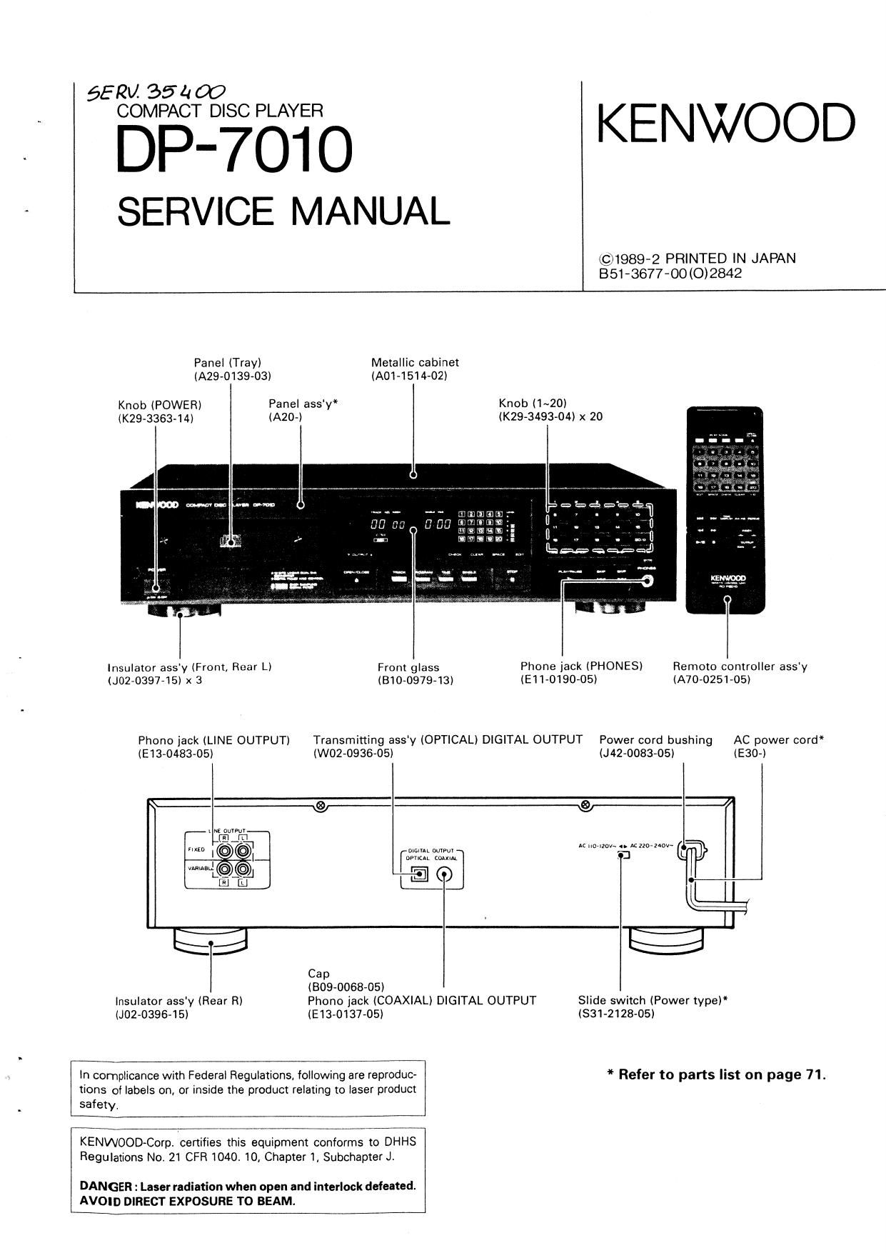
Metallic cabinet
(A01~1514»02)

Panel (Tray)
(A29v0139-03)

Knob (POWER) Panel assy*

(K29-3363-14l (AZO-l

From glass
(81070979713)

Insulator ass'y (Front, Rear LI
(J0270397715l x 3

Phone jack (LINE OUTPUT)

(E1370483705) (WM-0936705)

Transmitting ass'y (OPTICAL) DIGITAL OUTPUT Power cord bushing

Knob (l~20)
(K294149304) x 20

Phone jack (PHONES)
(EIIVDISO-OS)

Remote controller ass'y
(A7070251705)

AC power cord"
(J42»0083705) (E30~)

um WW.
(mm mum

EIO

19;
"J

Cap
(BOB-006805)

Insulator assy (Rear RI

(J0270396-15) (EB-0137705)

ln complicance with Federal Regulations. following are reproduc-
tions of labels on, or inside the product relating to laser product
safety.

KENWOOD-Corp. certifies this equipment conforms to DHHS
Regulations No. 21 CFR 1040. 10, Chapter I, Subchapter J.

DANGER : Laser radiation when open and interlock defeated.
I AVOID DIRECT EXPOSURE TO BEAM.

Phono jack (COAXIAL) DIGITAL OUTPUT

E2

Slide switch (Power type)
(Sm-2128705)

* Refer to parts list on page 71.

Page 2

DP-701O

CONTENTS

CONTROLS AND INDICATORS
SYSTEM CONNECTIONS .....
DISASSEMBLY FOR REPAIR
1. Removing the operetinn unit
2. Removing the tray .
3. Insulling the tray
A. Removing the pickup
BLOCK DIAGRAM
CIRCUIT DESCRIPTION
1. Dowiption of components.
. CD player unit (XSZ-ISTX-XX).
Set mode flowchart ..
Tut mode .
. Micropmeossor pPD'lSZ'IZACW-osz
(X32-137X-XX : ICI 6) ..... ..
. RF AMP. CXA1031M (XE-189005 ICI ..
7. Servo control CXAIZMS
iX32-137X-XX : I010)
8. Digital signel processor CXDI 12502
(X32-137X-XX : ICZOI


mpg)»

o

918-bit sari-l input DIA converter PCMSBP
IX32-137X-XX: )C'I 3,].-

10. Ex over-sampling digit-II I Iter SM5813AP
IX32- 137X- XX . I014)

11. D. P. A.C IC TC1'IGDOSAF- 8060
IX32-137X XX: I019) .......
MECHANISM OPERATION DESCRIPTION
1. Troy OPEN/CLOSE operation

2. Pickup chassis UP/DOWN movement

3. Gear installing position
ADJUSTMENT
REGLAGE
ABGLEICH .....
PC BOARD (COMPONENT SIDE VIEW) .
PC BOARD (FOIL SIDE VIEW)
SCHEMATIC DIAGRAM ......
EXPLODED VIEW (MECHANISM)
EXPLODED VIEW (UNIT)
PARTS LIST
SPECIFICATION


DP-7010
CONTROLS ANO INDICATORS

. ........................................................................
: Program Check Ind-cmor ,- Tme mums,
: SINGLE TIME
1 TOTAL TIME Musuc calendar II - 2o)
.
: mm M "d'cmr Ouwm ImI Indlcaior
.
.
: Program No. indium!
I
' r ---- "I | r--
: , "wax u." ,F:- .
3 TRACK No. Indvcalcr - H '"I '
E Disc ouI Indlcamr -
E I
E DISC indicelor -J
2 REPEAT IndIcanr
.
E Sectmn repel Indlcalov --' SPACE Mm,
1 EMPHASIS IndIcalOr g L ED" indicanr
k ...................................................... I ...................................
DISC my Remole conIrol ligm a a w Numenc keys (m - -,
receiving section D-solav WI" 0
W m. I mum». .
1... PHONE
)SCII

srop key (IE)

SKIP keys HE , IE)

PLAY/PAUSE key I : )

power; We" OPEN/CLOSE key IE3) J

Play mode selecior -1
[TRACK mode, PROGRAM mode, TIME mode. SINGLE mode)

Way/pa use Indlcnm


Manual Search keysIE| E I

mg

4-]

my. me. .

llll llllll

L EDIT key
SPACE key

CLEAR key

DECK mam sues

I 1
L REPEAT key

Tlme mspIay key
CHECK key

Page 12

DP-7010 DP-7010
CIRCUIT DESCRIPTION CIRCUIT DESCRIPTION

4. Test mode 4-2. Key and functions valid in thst mode
1-1. SWIM 3M 81 mod; _ ml mm by Fumlml 1nd: No. alum

Unlike prewous models, this mlcronruamr can be pm (I) meiw m , 0N
lo the test mode by iusx short-circuitinu the um piws even (2) kam m . V _ ON I"
in (he sel mode (normal condition). (However. the disc (3);. .M, _ on LI
must be nrmnl in lhe unit.) 1 FL

The (gs! made an also be initiated wilh the prwious Displayed Imllew mounds guacamole
melhod, l e by switching the power on wilh the (an pins non o! (I) (2) and (a).
shon-clrcuited. I I

my: Truck N0 isdiivllved
("Focusing sane ....... . . . . ON. _
2 CHECK l2) Tracking semi OFF. II-l _
(3) Fold am. V . DFF --I -I
IUFocusinu acrvo , DN. n I
3 CLEAR (2) Trucking am, on U H
(3) Fudsarvo . ,. . OFF,
(Focal-inn servo . OFF.
A 510? [ZlTudunq sumo . . OFF '7, I
(1) Foe-15mm ...... . OFF. L I
llual'wrabwl (l) Trly , . Opened.
" M (nu-v V, ........ cm I_/
5 REPEAT TM REPEAT function is unmlod when "is luv is closed by Drusilla L, 8
[he "IV. n

The Truck No. divaIY Ll ll .

In the STOP mi mow: lne pickup slightly «mam ma cum
6 » position a! disc

When ma serve is ON, ms the mck gain ID H"l

In ml STOP mode. move: me pickup IDMIV low-rd (ha innev
7 « nailion of am

When cud wvo Is ON, am the mck win to "L.

a »I Turn-IIFLdiQIIy Imus ON.
9 I« Tums .Il FL dilullv Ilmns OFF,
Jum luck: If shown MUN.
Tm m kly Kw l 2 3 4 . 5
;§:: " rulv No Number M luck: 1 « ls :2 «no
4 Drama: 5 N""" V Dlmion cum
'7 0 " 9 Kly 5 7 a 9 o
Numv nl luck: I 4 la 32 low
lair-cm" Imm
OPEN/(105E wrm in. my Mum man clan-1,Tnck No 2, a, 7 s, 10.x: .na
TNO.2,G,1I,I0,I: 1 ov HO 22m progmmduldlhfimmodlismulefl,
mflmfm 2 P MODE Truck No. 2. e, 7. a, m, I3 and 22 m programme and m w
8-! mac ' mode l: canal-d.

.-___.__I

18

19

Page 27

DP-7010 DP-7010
MECHANISM OPERATION DESCRIPTION ADJUSTMENT

. - - IIIPUT OUTPUT PLAYER ALIGKIEIT
3. Gear Installmg no IO» .0, E. samxc 5mm 5mm Pam um: rm: m
When re-insxauing the gear after removing it. mach The snows-mun pm 0.. In. polar rm.
gear at the posnion (0) shown in ma condition when the IN am an m o 1 m u an. «m
pickup chassis has been lowered. peter on to enter the .Ixfrncliun
(he tell lode, lnhu is correclly
Anvly 1h: xenmr Press the IAIIIAL S ahued lllh the RF
SEDIIOII of (he uvliuI 100m low the MI of 1.991
I LISIIII POIER - polar nelu an Ihe pickup mlllxdt. ~ or more nd (A)
menu lens. Press In: L'IIECK key the TE ('er open)
to chat Ihll {In Ll] level of I SVD'D
elil; Iilhl Than. or lore. (he Dukuv
conI'ir- In! the u acceptable.

diwlav is' a: '

Comm . frequency Press the Sm! m I.
2 Von A :ounur m FLCII (191). nd co-fu'l Ih-I (Hum) t mm: (b)
(xrnrlm) he diwlu n m .

9" m mm he
Connect n oscillcseop to am m my,

as ronm. um . an: m mum heuaen
mum mo: rm dim cm: RY mu In. my by Is BALAICE upper m 10m
a mule: Tm 4 (m-xm m) mum it n», mm m valiant Lo
cm: r2 menus: me one (xzsrmn) at DC= asv
(mum m m n m, mm. mm
the diwlty I 'IIJ'.
Connect In oscillnlcup
Gm u fallen. Frau m rm
rows mu In: due an; as m. an - um rs mum
4 mum Type A (xza-ma m) the am! y m Oph- eyeplllern (a)
. . on. re is as . (mayo)
Hg. 4 Genrmstallmg position (xsz-mn m m 1)
Tel! disc
I'm l mm: an m m cns Iron m PLAY
Apply signal of m 1, m which conne: m. Conlirl mt FOCLS cm
5 FOCUS um um. u 5v: Io .n olciIIcuope {he diwlu in 5mm <.)
cls pin 2' or an ac voluoler. n' as '. (mrmn)
mum) (Imam)
Yul mu
Type 4 coma an m to en Frau ll: PLAV
mu m .1 or m a, lo lluch connec m. mm. um meme cm
6 mcnm um um, mm: m u. oscilloscope lh: amm m 5mm (9)
m m 4 or an AC voluelu, n' as (x12 mu)
(Hum) (mum)
1m disc 5mm .n distortion Pm me 1sz van L
1 m DISTDRIIOI mu me: In line mm mm mm mm mm. dislorlmn u)
(Isa) termn:I(FIXED). in um 5015 {HZ-1170)
Test am can... u. diszamon pm m m . m I.
a mo msmmmn Type 4 me: :0 m cum: m mm m4: Inn-u. dulonion (r)
(183) mummxm. n. ma: nu (mrmo)
(Hum) '19: I due. 50" "SOS IB Tau II: or equiv-Ianlv
m: Around "was? Dr lo.
48 49