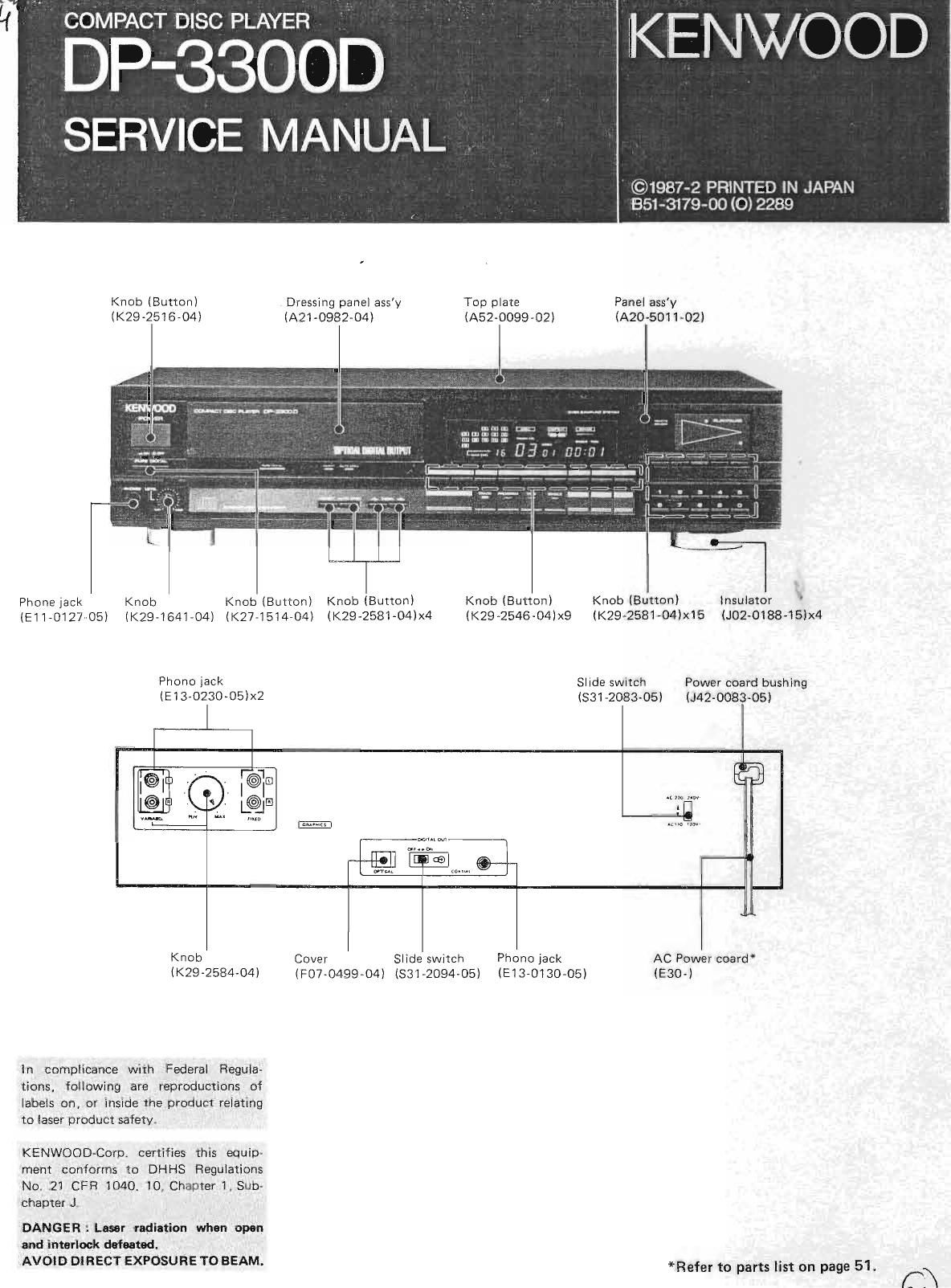
Kenwood DP 3300 D Service Manual

This is the 63 pages manual for Kenwood DP 3300 D Service Manual.
Read or download the pdf for free. If you want to contribute, please mail your pdfs to info@audioservicemanuals.com.

Page: 1 / 63
left right
Kenwood DP 3300 D Service Manual

Extracted text from Kenwood DP 3300 D Service Manual (Ocr-read)


Page 1

1. 2. 4. Remove eight screws db retaining the side panels to the chassis, and remove the side panels. Then remove six screws @ tixing the top panel to the chassis frame, and remove the top panel. DISASSEMBLY FOR HEPAIR the Mechanism ass'y the tray toward the Move the gear on the left side of with your finger ( @ ) and Putt tront ( @ ). \a@ @ 5. Pull up the four claws on the tray panel in the direction of the arrows and remove the tray panel by pulling it ouT in the ciirection @ . Push the tray back ( G! ) Disconnect three connectors (CN3, CN4, CN5) from the CD plaver unit (X32-1090-11) (G ). Remove four screws @ retaining the Mechanism ass'y and remove the Mechanism ass'y by pulling it slightly backward thenrupward ( GF ).

Page 2

2 3 5 77 7 10 10 12 12 12 12 12 12 12 121313 13 13 16 16 16 17 6-3. Explanationof functions ...... 14 7. Signal processor lG : GX23035 (X32-1090-11 :lC3). 14 7-1. Block diagram 14 7-2. Explanation of terminals 15 8. Digital output signal demodulator lC : CXDl075P 7 8 9 9 (X32-1090-11 : lC9) . B-1 . Block diagram B-2. Terminal connection diagram 8-3. Explanation of terminals 17 ...20 21 21 20 20 24 27 4. 5. E] E] E] E] tr) I!]E)EElE)u@gE@ EgUE@ @ t@r ,-l l-t *' L, L, i.[] CO NTENTS/THANSPO RTATI O N SCREW TRANSPORTATION SCREW DISASSEMBLY FOR REPAIR BLOCK DIAGRAM CIRCUIT DESCRIPTION 1. Description of components . . 1-1 . DAC UN rT (X25-2860-1 1) . . . . 1_2. CONTROL UNIT (x29-1780-00). . .. 1-3. CD PLAYER UNIT (X32-1090-11) ..... . 2, Circuit description 2-1. DAC lnterface circuit (X25-286O-11) . . . . . 2-2. Distortion correction circuit lx25=2860-11).... 2-3. Dropout control circuit (X29-1780-00) Dual D Flip-Ffop lC : TC74HC74F (X25-2850-00 : lCl,lC4) 3-1 . Block diagram 3-2. Truth table . Hex D Flip-Flop lC : TC74HC174F (X25-2850-00 : lC3) 4-1 . Terminal connection diagram 4-2. Truth table . DA Converter : PCM56P-K (X25-2860-1 1 z lCl,lC2l 5-1 . Block diagram/Terminal connection li^^-^- u tout dI l S-2. ExJtanation of terminals Digitalfifter: SM58O4B (X25-2860-11 : lC4) . . 6-1 . Block diagram 6-2. Explanation of termlnals TRANSPOBTATION SCREW Before operation, remove the two red screws attached to the bottom of the unit used during transport from the factory. Remove both screws using a coin, etc. and, after removing, retain them together with the Warranty card and other documents. When the unit is to be trans- ported again, be sure replace the two screws to their origi- nal position. ATTACHING THE TRANSPORTATION SCREWS 1. Turn the power ON without loading disc. 2. Turn OFF the power after the display shows the follow- inq indication. 8-4. Explanation of functions . . . 9. Microcomputer : PPD75208CW-040 (X32-1090'11 : lCl1) 9-1 . Terminal connection diagram 9-2. Explanation of terminals . . . ADJUSTMENT ... Adjustment Q6nlrna I rEgrqgs Abgleich Description of Signal Waveform, Connection of Measuring Instruments 30 VOLTAGECHECKTABLE ... 34 Pc BoARD (CoMPONENT slDE vtEvQ . . . . 1? - pcBoARD(FO|LSIDEVIEW) ..... .... 38 SCHEMATIC DIAGRAM 41 EXPLODEDVIEW(MECHANISM) ...49 EXPLODEDVIEW(UNIT) .... 50 PARTS LIST . 51 SPECIFICATIONS . BACK COVER 3. Install the transportation screws.

Page 18

CIRCUIT DESCRIPTION o Input signal description (ex, CX23035) 1) Digiul audio data This LSI uses 16-bit serial digital audio data' and the data bits are arranged from backward with respect to LRCK. As the period of clock BCK is equal to the data bit rate, more than 16 clocks are required for each word' For example, when the signal processor LSI connected is CX23035, which is a CD signal processor, LRCK is "H" during the L-ch audio data and "L" during the R-ch audio data, and the audio data is shifted in MSB-first mode at the fall of BCK. These Jactors can be set by the above- mentioned selector Pins. LRCK DATA BCK 3) Channel status data By connecting D2 (pin 26) with the write frame clock output terminal (wFcK) of the cD LSl, D3 (pin 25) with the subcode sync S0 + 51 output terminal (SCOR)' D4 lpin 24 with the subcode O output terminal (SUBO) and CRCK (pin 6) with the subcode O error flag terminal (CRCF), it becomes possible to read respectively the lD0' iot, COpv lNHlBlT and EMPHASIS information from SUBO and to set them on the specified positions of the C-bit data. However, when there is no terminal correspond- ing to cRCF, it shall be f ixed a|"H" ' 2) Master clock When a 1-sample/48-clock one-chip CD lC (CX23035) is used, a X'tal oscillator of 3 x 128Fs = 16'9344MH2 shall be connected across XTAL (pin 13) and EXTAL (pin 14). The internal circuitray of this LSI lC uses the 1/3 clock, which is 5.6MHz, as the master clock'whilethe CD uses the output from 192Fs (pin 12) as the master clock (3 x 12BFsl2 = 8.4672MH21. It is also possible to connect a 128Fs (5'6448MH2) X'tal oscillator across XTAL and EXTAL and to use it as the common master clock with the signal processor LSI. Fig.8-3 The category code (subcode bits 9 and 10) is input in DC via Cg (pin 16) and CiO (pin 5)' With the CD' the category code is (C9, C10) = (1' 0) so the bits are fixed at C9 = "H" and C10 = "L"' Note : D4 (SUBO) is read at the rise of D2 (WFCK)' latched and, when CRCF = "H"' loaded as the C'bit data at the fall of D3 (SCORI' lf CRCF = "L" ' the Previous value is held' With this LSl, it is also possible to input the chanel status data in parallel. In this case' lDO' lD1' COPY' EM- PHASIS and category code are input respectively to D4' D5, D6, D7 and C9 and C10 bv direct DC inputs' WFCK EXCKSBSO 18 SYNC. PATTERN Fig. 8-4

Page 27

! I P ABG I-EICI-I 1. Abgleich NR C EG Ell STA ND I] I NGA liGS- E I IiSTELI,UNC AUSG,{NGS- FI NCTFI I IINN SP I ELER_ E I NSTEI,I,IIN('; AbGLE I UII- PIINI(T E ABGI,E I CHEI{ FiiR ABB YCO.D I IiSTELLUN( Einen Frequenzziihler zrrischen TPll (CND) von X32-1090-11 und TP10 (PLCI{) ancnhl ioRon Triiger getjffnet oder Stop-Betriebsart Den I(ern der Spule von L2 von X32-1090-11 rl //) dr6hon' 4.32}{H (a) a PRUFUNG DDR LASERLEISTUI,IG (lenn PU defek u sein scheint Ei nen 0ptikleistungsmeter auf den abnehner setzen. 'I raSer -geoll net 'P8 von X32-1090-11(A/4. an GND ansch I i eBen. DIn der Test-Beirieb- sart die CHECI{-Taste ruf 0N stel len. Der Trii Ier tiffnet sich, und de: .D vird auf 0N cestel lf kzeptabel, wenn zwischen 100 pY und 200 rzt.(b) RF-YERSATZ- PRU FU NG Ein 0szilloskop an Stift 2 (RF) von Cll4 von X29-1780-00 anschl ieBen. GND des 0szi I Ioskops an TPl (GND) cncnh I i aRpn Trager getjffnet oder Stop-Betriebsart Akzeptable, $enn etrYa -0. 70 (Y) (c) 4 TESTl{ODUS- E i I{STELLUNC Testdisc Tvpe 4 ruf Trager lege und Laden .llr.hfiih"." Den Stecker von CNl0 von X32-1090-11(A/4) (urzschl ieBen. Den POliER-Schalter auf OFF und dann wiede. auf 0il stellen. Auf dem Display muB 01 oo anSezeiSt rerden. (d) Trtl{0DNT IAL- DI NSTELLUNG lestdisc Tvpe 4 tuf TrriSer lege und Laden durchfilhren- Ein 0szilloskop an Stift 2 (RF) von CN4 von X29-1 ?80-00 anschlieBen. Die CHEC(-Taste driicken. Der Laser fokussiert (Tpct nndr<) I nnensechskant- schtaube unter Mprhan i

Page 44

q !obdE ocd[ .-m-No96@ sl s+ st5+ sTgfs Qr@6a9oN--No 9ooa;ooooooo3338;3338;;f RA O4 RAO5 RAO6 RA O7 RA O8 RAOq RA IO RAI RA !r'8 RACS c4 u TTA g@r@o @@@@@ :i'-.-, IEc pn'/EE -:: o r o VDD N SRCH ISET, , fT VEE 02 l (r /3, I +z't.;1! ata z.zx A o r o &- L___f-;Q2 t2/3 ) 5.? lMon rNvstl >k -S o N o c o o c @ o o z r 5 t2/?l I /2) a t0) lo. ,1ZkQ CU04P c00P cOBP 974Pi14 STA34? M [] %/ BU4O53B CX D1O75P 15 PPD4OS3BC s- ---t;- -^'"";->> -/'a *@,,@ ,, AN7805F fvr521BP M51 951 ASL

Page 56

PART$ LIST x New Pants Parts wlthout Parts No. are not supplled' LeSart]clesnonment]onnesdanslePartsNo,nesontpasfournls. Telle ohne Parts No. wenden nicnt gellefert' it1! Desti- nation {rH Descr iPt ion *$ F" *,/ffi, H Parts No. gFF"*E Ref . No' #ffR#-‚¬ VR5I lTr _-, F:.1 Pt-l1 F r-{;l Dl -4 Di -4 U*J roIJJ I LJDB D-‚¬] D].;i ' 1.3 nr.f 1:2 Dtc- ! r'J 014 D14 Fr 1i- 1054-05 R1U-i0il2--05 551--2il?4-05 1':75- U035- U5 r95 -0036 -05 Flz55. 15 ( ti ) RDs. 1J5(B) t-lzs10N ( [i ) fiDl0[5(B) r f-f' 1 ?-? IJJT'9 I'RiI'INING f:'NI-. (L5B ADJ)r;s trru-r l ErlrlEf;l (LINE 8u1 ) f'lA6N[l-Ir:: RELAY EFTN 158LA1NR NF.TN ISNLAINfi ZENEI1 D]EDI: ZENER DINDE ZENEI1 DIEDE ZENEII I]I8DE D I Ni]E D INDE I] I NDE DINDI Zf:|'lEfi DINDE ZENEii DINI]E Dl itDE DIEi]E t.r: ( IIA r:.tlNVEt{TEFt ) I I:: ( NF AI{P XZ ) DUAL FET i r ( tJF At'ttr xi ) ir-:tnIGITAL- FILTEti F:Efi r-:D) t. L: ( t-lEX L NvEftTEft ) iirvur-racr REGULAINFI/ +24V) i i t vbr-roGE rIEGULA-I-NI1/ -r--‚¬'\' ) II: ( D-F:Li[:';LNP ) r I t iiunl Lj I NARY riNL,N-rER ) IL.(HEX iNVERTER) TRANS I 51 8R i:E I TITANS I STNIi I]I6]1AL lRAI.I5I5TER ,b *: 1E !-J ,1. ,t. U.I :JD15rf'l Ir_. J. r f_ I r-:3 - 10 It::l1 ' li 11 1.3 i l-'14 It:.1 5 Ir_.1d: lr- { a ll-. J. I 1t::18, 1? IL.iO I l::21 rl1 -4 l;!5 ' 6 t-:!'7 ' B rJ10 - 1:1 r;t14 .1. n, .+-.]..t. '1. !i IJJI IU I t^f^ 1 'a-J IJ:)IJJ 1551?6 HZ510N(E) RUlUEi.i(F) 1 i: r-l 1 -:i -1IJJI'JJ155176 fr[:m56F - K. NJfl:i53ill-D UITA6BI{A NJI'15532D-D 5115404E -l-t::-l4flt::CI4 i: Tfi ??LOO6fr 1A-iillou6AF' Tt::741'lt:.?4P -r[:?411[.3?3i:' Tr:'741-{r:04F i5l:'t45(A) (l:.1,F ) c5K1?0(v) l5t-:?45(A)(l'.!'F ) IIT t_:1 1 4Y[:'F z3A 733 ( Al l_[!E:-l IRANS I'J INiI CD PLAYER UNIT (X32-1090-11) l.1r tl' louF:t'tF ii00F[r t'lF 4 ?ilOF.'F: NF.- ELEL 1UF f'fft 0. 0t?UF rEFiAl'I][ CI. CIlUF t'l ntF-rlE': louF t5t^'v r.rr= --- 0. tl15UF J ,l:-uttRNt'- 0. 010uF Z r-frrnm t r-: 4?F F J t'tF l5OoFF { rlr' 0. 4?UF J 'N'F'--.ELEr-: lurr 50t^lv r::rnRmtr: 0.0t0uF z lErtnmiu 33t-'F J r:ERAr'1It 5. 0frF l- LrnnNt':, leoF'F J r-:innmrr: ee0oPF K' iEnnr'|tl, 22oCIPFj K t::F-?21:v 1l-{ 104J L:F9IF V i li;:22J r:F:?2FU 1ll4?aJ I i.ln- 134?-'05t_:FrgiFv 1Fl273J r-‚¬, I I lr-'11-!le:i-P:':i I I lt;:2q;1rll.9*:ijB I i lr_:rr4_1y1f1111{a..l i I lt::r-asr1if1,9lf']io I I ir::c+':r'sl1l-t47oJ c1i I I lrllilYltll!+{ ,:ii i i ir:12ary1:14itr ai3 I I lr_:ro-r:1?:91 ':i+ i I lr-.x:asrr'ry1.0_i,1 ii:l I I i tr-:a:ruJ1l-133CIJ r::le, I I l r:r-:+st=uJ_11q59';ii-r I I lr:r:asruJlt1iili'iie I I lt:r:+115111??ll':i:i4 | I lt:r:a=rnlHrzir * 0 {, t\7t\. E: Scandrnavia & EuroPe K: USA U: PX(Far East, Hawaii) T:England UE:MFES(EuroPe) X:AustraliaP: Canada W:EuroPe M: Other Areas 54 I indicates sa{ety critical components'