Kenwood DP 28 Service Manual

This is the 32 pages manual for Kenwood DP 28 Service Manual.
Read or download the pdf for free. If you want to contribute, please mail your pdfs to info@audioservicemanuals.com.

Page: 1 / 32
left right
Kenwood DP 28 Service Manual

Extracted text from Kenwood DP 28 Service Manual (Ocr-read)


Page 1

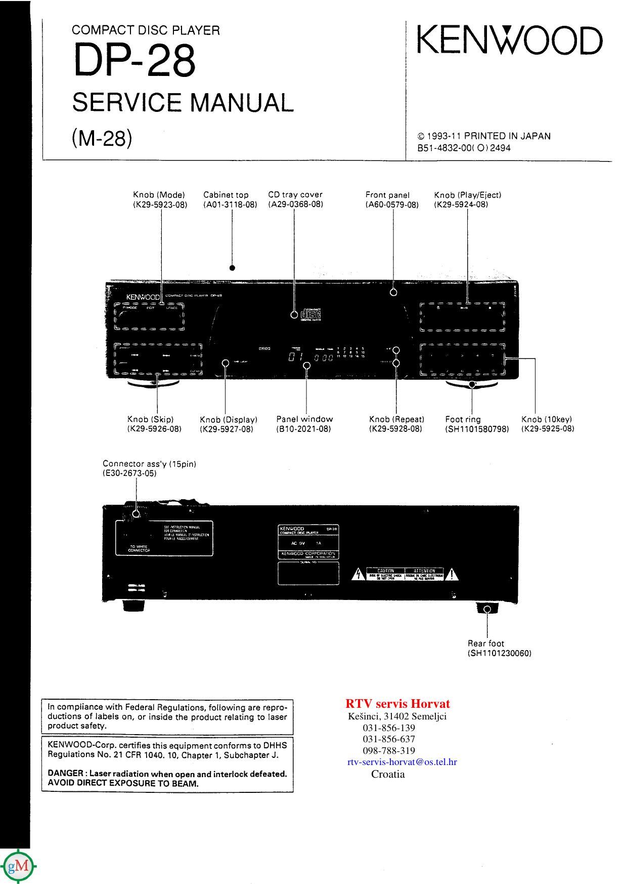
COMPACT D lSC PLAYER

DP- 2 8
SERVICE MANUAL
(M_28) («3199341 PRINTED IN JAPAN

851-4832-00< O) 2494

KENWOOD

Knob (Model Cabinet top CD tray cover Front panel Knob (Play/Eject)
(K29-5923-OB) (A01-3118-08) (A29-0368-08) (A60-0579-08) (KN-5924.08)

Knob (Skip) Knob (Display) Panel window Knob (Repeat) Foot ring Knob llOkey)
lK29-5926-OB) (Km-592108) (810v2021-08) (K295925308) (SH1101580798) lK29-5925-08)

Connector assy (15pm)
(E30«2673-05)

Rear foot
(8H1 101230060)

In compliance with Federal Regulations) following are repro- RTV serViS Horvat
ductions of labels on, or inside the product relating to laser Ke§inci, 31402 Semeljci
product safety. OBLSSG- 139

03 l >856»637
098488-319
rtV-servis-horvat@os.tel.hr

DANGER : Laser radiation when open and interlock defeated. Croatia
AVO|D DIRECT EXPOSURE TO BEAM.

KENWOOD-CorpV certifies this equipment conforms to DHHS
Regulations No 21 CFR 1040. 10, Chapter 1, Subchapter J.

Page 2

DP-28

CONTENTS/ACCESSORIES


CONTENTS

ACCESSORIES ....2 MECHANISM OPERATION DESCRIPTION
CONTROL ........... 3 ADJUSTMENT ..........................................
REMOTE CONTROL ....4 PC BOARD (COMPONENT SIDE VIEW) ..
DISASSEMBLY FOR REPAIR .. ...5 SCHEMATIC DIAGRAM ....................

BLOCK DIAGRAM .................... ...7 EXPLODED VIEW (MECHANISM) .

CIRCUIT DESCRIPTION EXPLODED VIEW (UNIT)

1. Test Mode ........................................ ...8 PARTS LIST ...........
2. Microprocessor : IX2248AF (IC4) SPECIFICATIONS .-

. ACCESSORIES
i N
i (FM indoor antenna ...........1 - AM (MW, LW) loop antenna ...1 - Loop antenna stand ..........1 - Antenna adaptor (750mm) ,..'l
( (Tao-017505) (HO-0195435) (MS-363605) (T90-O185-05)
i
i t
.
- Batteries (RS/AA) ................ 2 - Renters control unit ........... 1 ' AC MUG MW (M W03 MY) 1
I-) (A700956-05) : Pic-28 (Em-011505)
U0 5 II 4",
a), my. is I
6, 0
Battery cover (A090146«08) (Except for some areas)
For the unit with a European AC
K plug in areas other than Europe. 1
All accessories are packed with FIX-28.
System name Cassette receiver CD player Speaker DP-28 instruction manual
(860453908) E. F. G. D, l, S : E
M-23 8X48 DPQS LS-28 (EGO-154008) English : X, T
(EGO-154108) Eng. Spa. Chi. : M, i
Graphic equalizer
Option GE-zs

Note related to transportation and movement

Before transporting or moving the CD PLAYER, carry out the (o|~

» - l 2 3 I =
low-n9 operations. a 7 a e in
. -. _. 1 I I" 1" 1 2 i: 1415
1. Turn the power 0N but do not load a disc. I I l_l 1:, I :l l_ .3 17 «a m 20
2. Wait a law seconds and verify that the dispIay shown ap-
pears.

3. Turn the power OFF (RX-28).

Page 16

DP-28

ADJUSTMENT

RF level, TE waveform

- RF signal and E.Spot signal in test mode (PLAYlv
. If the diffraclion grating has been adlusted properly, the
cm influence of triggering is observed on the ESQOI waveform

RF signal of approx. l8us after RF signal, in the form of a projection

«(NW


._ 0W)

CH2
TE siganl

- RF Signal and T.Error signal; in test mode lFocusmg ONli
CH1 (Disc We 4)
RF signal . Ad|ust T Error so that the waveform is symmetrical above
and below 0V (VR 1)

CH2
TE signal

16