Kenwood DP 1520 Service Manual

This is the 47 pages manual for Kenwood DP 1520 Service Manual.
Read or download the pdf for free. If you want to contribute, please mail your pdfs to info@audioservicemanuals.com.

Page: 1 / 47
left right
Kenwood DP 1520 Service Manual

Extracted text from Kenwood DP 1520 Service Manual (Ocr-read)


Page 1

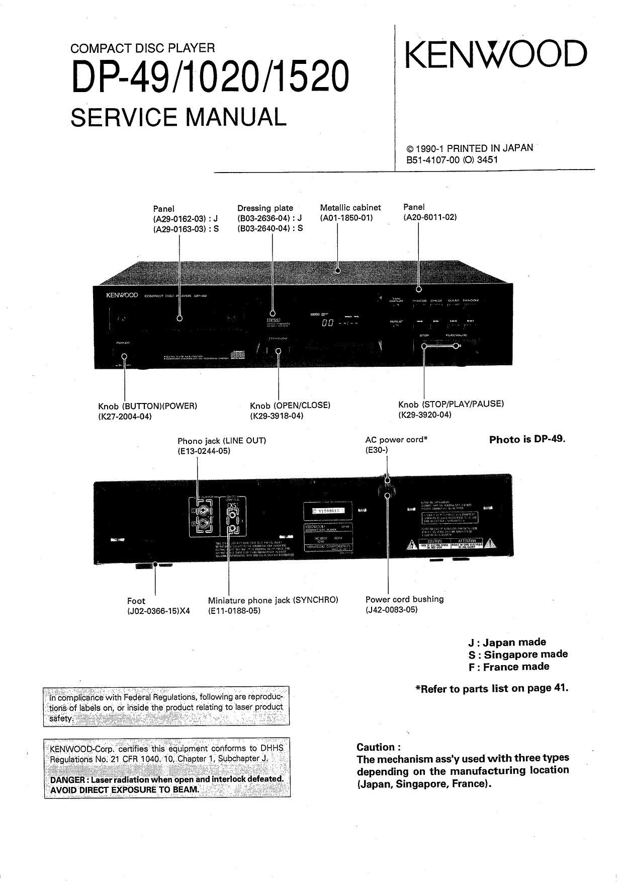
EMETZEIIEézo/Iszo KENWOOD
SERVICE MANUAL

©1990~1 PRINTED IN JAPAN '
851-4107-00 (0) S451

Panel Dressing plate Metallic cabinet Panel
(A29-0162-03I : J (BOB-26364) : J (A01~1850-O1I IA20-6011-02)
IA29-0163-03) : S (BOB-2640434) : S

KENV. (JOD v:

Knob (BUTTONMPOWER) Knob (OPEN/CLOSE) Knob ISTOP/PLAY/PAUSE)

IK27-2004-04) (K29-3918-04) (K29-3920-04I
Phone jack (LINE OUT) AC power cord* Photo is DP-49.
(E13-0244-05) (E30-I

Foot Miniature phone jack (SYNCHROI Power cord bushing
(J02~0366-15)X4 IE1 $018805) (J42-0083-05)

J : Japan made
6 : Singapore made
F : France made

*Refer to parts list on page 41.

Caution :

. . I The mechanism ass'y used with three types
DANGER : Lasenadamn when open an ' \ depending on the manufacturing location

9 AVOID DIRECT EXPOSURE To BEAM 3 V . (Japan, Slngapore, France).

Page 2

DP-49/ 1020/1520

CONTENTS

DISASSEMBLY FOR REPAIR
1. Removing the outside fittings ........ 4
2. Removing and installing the tray ..... 6
3. Removing the pickup (Japan made) ............. 8
3. Removing the pickup
(Singapore and France made) .......... 9
BLOCK DIAGRAM ..................................
CIRCUIT DESCRIPTION

1. Description of components
2. Test mode ...............................
3. Microprocessor : uPD75212ACW-185

MECHANISM OPERATION DESCRIPTION .......... 25

1. Tray OPEN/CLOSE operation ...................... 26
2. Pickup chassis UPIDOWN movement .

3. Gear installing position
ADJUSTMENT .......
VOLTAGE TABLE
PC BOARD .....................
SCHEMATIC DIAGRAM...

EXPLODED VIEW (MECHANISM)

:JAPAN MEDE .................................

EXPLODED VIEW (MECHANISM)


(X32-1610-XX: I04) ................ : SINGAPORE MADE ......................................... 38
4. RF AMP : CXA1081$ EXPLODED VIEW (MECHANISM)
(X32-1610-XX: IC1) ....................................... 16 : FRANCE MADE .............
5. Servo control : CXA1244S EXPLODED VIEW (UNIT)
(X32-1610-XX : ICZ) ....................................... 18 PARTS LIST .........................
6. Digital signal processor : CXD1167Q SPECIFICATIONS
(X32-1610-XX : IC3) ............ é .......................... 20 DP-49, DP-1020 ..
7. Custum IC: KASO1 (HIC) DP-1520 ..............
(X32-1610-XX : I09) .....
JAPAN MADE SINGAPORE MADE FRANCE MADE
DF-4s CONTROL UNIT x32-1510-10 (K,P) X32-1630-IO (K) -
X32-1610-21 (M)
X32-1610-71 (X)
MECHANISM ASS'Y X92-137005 X92-I400-05 (K) -
DP-1020 CONTROL UNIT X32-1610-11 (P) K32-1632-71(E,T) X32-1652-70 (E.T)
X32-1610-22 (M,Y)
X32-1610-72 (X)
MECHANISM ASS'Y X924370-05 X92-14oo-05 X92-1410-00
DP-1520 CONTROL UNIT X32-1610-12 (K) X32463041 (K) -
MECHANISM ASSY X92-1370-05 X92-I4oo-05 -
NOTE :

3models are written in this manual. Before using this manual, please check manufactur-
ing place and PC board ass'y number.
Control PC board ass'y (X32-) parts list (page 45)is written the parts for all of 3models.
Reler to comparision table in schematic diagram.

Page 4

Unscrew th

Page 6

DP-49/ 1020/1520

DISASSEMBLY FOR REPAIR

2. Removing and Installing the Tray

2-1. Removing the tray

* Open the disc tray and turn the power OFF.

1. Push the tray gradually into the unit (0) by your
hand In this condition, the gearwill be released (9 l.

2. Push the rear end of the tray toward the front to
remove the tray until it stops (9 ).


3. Release the two stoppers (0 ) and take out the tray
front the unit.

4. When removing the tray, release the stoppers in the
direction of the arrow ( 6 ) to prevent it from engag-
ing with the sub panel.

Page 25

DP-49/ 1020/ 1520

MECHANISM OPERATION DESCRIPTION

Mechanism Operation Description

Fig. 1 shows the relationship of mechanisms in the STOP
mode. The OPEN/CLOSE operation of the mechanism and
the UP/DOWN operation of (he pickup chassis when
loading the disc are description below.
Note 1 : The black arrow (OPEN) and the white arrow
(CLOSE) in the operation description have the following
meanings:
Black arrow (OPEN) : Tray opening direction

(Tray OPEN)
White arrow (CLOSE) : Tray closing direction
(Tray CLOSE) |

Note 2 : Figures in the bracket ( ) in the operation
description or accompanied with the part name in the
diagram show the reference numbers in the Exploded View.

DC motor (60)

Gear (21)

Gear (16)

Gear (17)

Lever rotary
switch (56)

Slider (14) Pickup (49) Tray (52) Pickup chassis (3)

Gear (19)

Gear (20)

Gear (18)

Fig. 1 Tray closed status

25

Page 26

DP-49/1020/1520
MECHANISM OPERATION DESCRIPTION

1. Tray OPEN/CLOSE Operation

By the rotation of the motor (0), the gear (9) is
rotated and the tray starts OPEN/CLOSE (9) operation.
The OPEN/CLOSE operation stops when the protrusion
of the gear comes in contact with the detection switch

(oi

_ Lever rotary
switch

Protrusion
Fig. 2 Tray OPEN/CLOSE operation

2. Pickup Chassis UP/DOWN Movement

Accompanied with the OPEN/CLOSE operation, the
iever is shifted (a) by the rotation of the gear (0 ).
Along with the grooves in the lever. the pickup chassis
moves up and down (6).

Pickup chassis
# OPEN

E
ii}

Pickup chassis

Groove

Fig. 3 Pickup chassis UP/DOWN movement

26