Kenwood DP 1100 D Service Manual

This is the 30 pages manual for Kenwood DP 1100 D Service Manual.
Read or download the pdf for free. If you want to contribute, please mail your pdfs to info@audioservicemanuals.com.

Page: 1 / 30
left right
Kenwood DP 1100 D Service Manual

Extracted text from Kenwood DP 1100 D Service Manual (Ocr-read)


Page 1

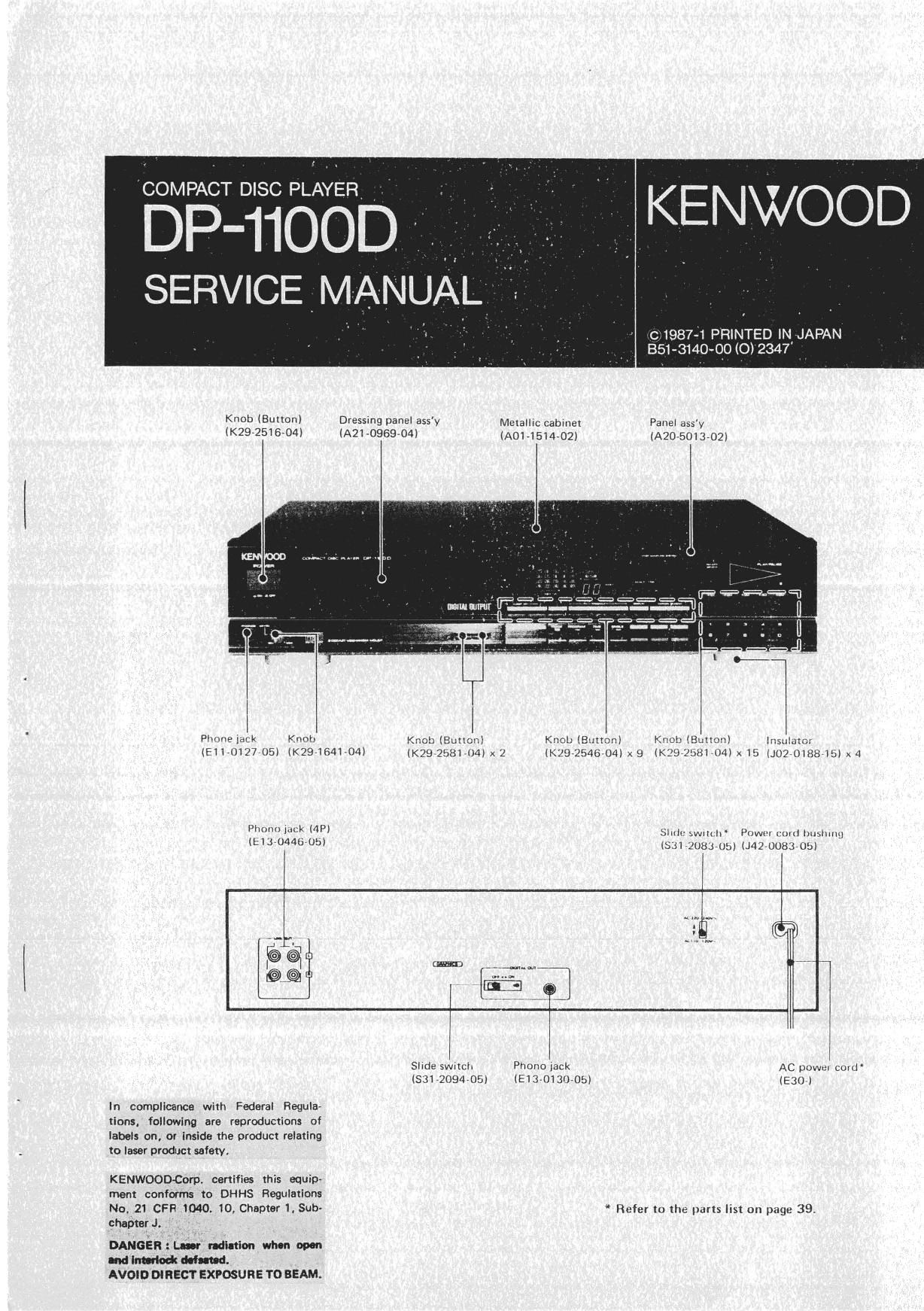
COMELDIfiSSD KENWQOD

SERVICE MANUAL

0198741 PRINTED IN, JAPAN
351-3140-90 (0) 2347

Knob (Button) Dressing panel ass'y Melalllc cabinet Panel aas'y
(K292516704) (Am-0969704) (ADI-151432) (A2075013702l

Plume lack Knob \: Knoll (Buncn) Knub (8111mm) Insulatar
{EILOIZTUBI (294641-040 , ' (K292546704) x9 IK 9 To! 04Ix15 (J070I881tx) x 4

Ihnlvn 5 MP) smuv swllth inm mm mum
(turuaao um (5:51 2083Mb) (#1270083 ubl

l [@23th

« l
l l

Sllde sthch P710110 lack AC powul COHJ
1531-2094705! (EIJ-OISIJ-Obl IE307)

In complicance with Federal Regula-
tlons. following are reproductions of
labels on, or Inside the product relating
to laser product safety.

KENWOOD-Corp. certifies (his equip

ment confolms to DHHS Regulations

No. 21 CFFI 1040. 10, Chap! 1, 5011 " Refer In Ihe parts list on page 397
chapterJ.

DANG'EnzL-uu ndmaon Mun upon

and Inn-Ind: Maud.
AVOID DIRECT EXPOSURE TO BEAM.

Page 2

DP-11OOD

CDNTENTS/TBANSPD RTATION SCREW

TRANSPORTATION SCREWS ................. z 4. Hex D Fliva|Op Ic ; TC74H174F (xzs-zasom :

DISASSEMBLV FOR REPAIR D . 3 Ica) ...................... .. 13

BLOCK DIAGRAM 5 471. TermmaI connechun dIagram . _ _ 13

CIRCUIT DESCRIPTION . 1 4-2. Trulhiable , 13

1. Dmripxion of components ......... . 7 ADJUSTMENT 14

I-I CONTROL UNITIX29-1780700) . . 7 AdIusUnenl ., 14

172 co PLAYER UNITIXSZHDOH) .' ..... 7 Héglage.u ., 17

173 DIGITAL SIGNAL PROCESSING UNIT Abglelch .. . . .. zo

Ixaznzo-on .................... 3 Descnpnan oI SIgnal Wavemrm, Connecuon oI

z. Diginlompuuignlldemodulatm IC : CXD1D75P Measurmg Instrumenls. 23

(xv-110041 :ICB) .................... 9 VOLTAGE CHECK TABLE . . D . 26

24 BIock dIagram ............. . 9 Pc ROARD (COMPONENTSIDE VIEW) . . 27

272 Termmal conneclmn dIagram . I . D 9 Pc BOARD (FOILSIDE VIEW) ........ . 29

2-3 Explanahon onermmaIs . .10 SCHEMATIC DIAGRAM . .. _ 31

24V Epranamn m luncnons I , , 11 SCHEMATIC DIAGRAM. . . 35

3 Dual O Flip-Flop IC : Tc74H7AE 25235001 : EXPLODED VIEw (MECHANISM) D . 37

mu 1: EXPLODED VIEw (UNIT) . . . . . . . 38

34 Block dIagram .. . . 13 PARTS LIST .......... . D . 39

3~2 mm mm ...... . .............. 13 SPECIFICATIONS ................ BACK COVER

TRANSPORTATION SCREW

Before OperatIon, remove me me Ied Screws anached Q

10 The bonum of The unIT used dunng Transpon from the
factory Remove both screws usmg a cum, em and, when
\he uml Is {0 be transponed agaIn, be suIe reDlace ms TWO
screws lo merr OrIgInaI Dosmorr

ATTACHING THE TRANSPORTATION SCREWS

I Turn me pOwev ON wIThom Ioadmg dIsc

2 Turn OFF \he power after me duspiay shows me IOHOwV
Ing IndIcaTIon

3 InsxaH (he Iransportauon screws