Kenwood DP 1020 Service Manual

This is the 47 pages manual for Kenwood DP 1020 Service Manual.
Read or download the pdf for free. If you want to contribute, please mail your pdfs to info@audioservicemanuals.com.

Page: 1 / 47
left right
Kenwood DP 1020 Service Manual

Extracted text from Kenwood DP 1020 Service Manual (Ocr-read)


Page 1

EMETZEIIEézo/Iszo KENWOOD
SERVICE MANUAL

©1990~1 PRINTED IN JAPAN '
851-4107-00 (0) S451

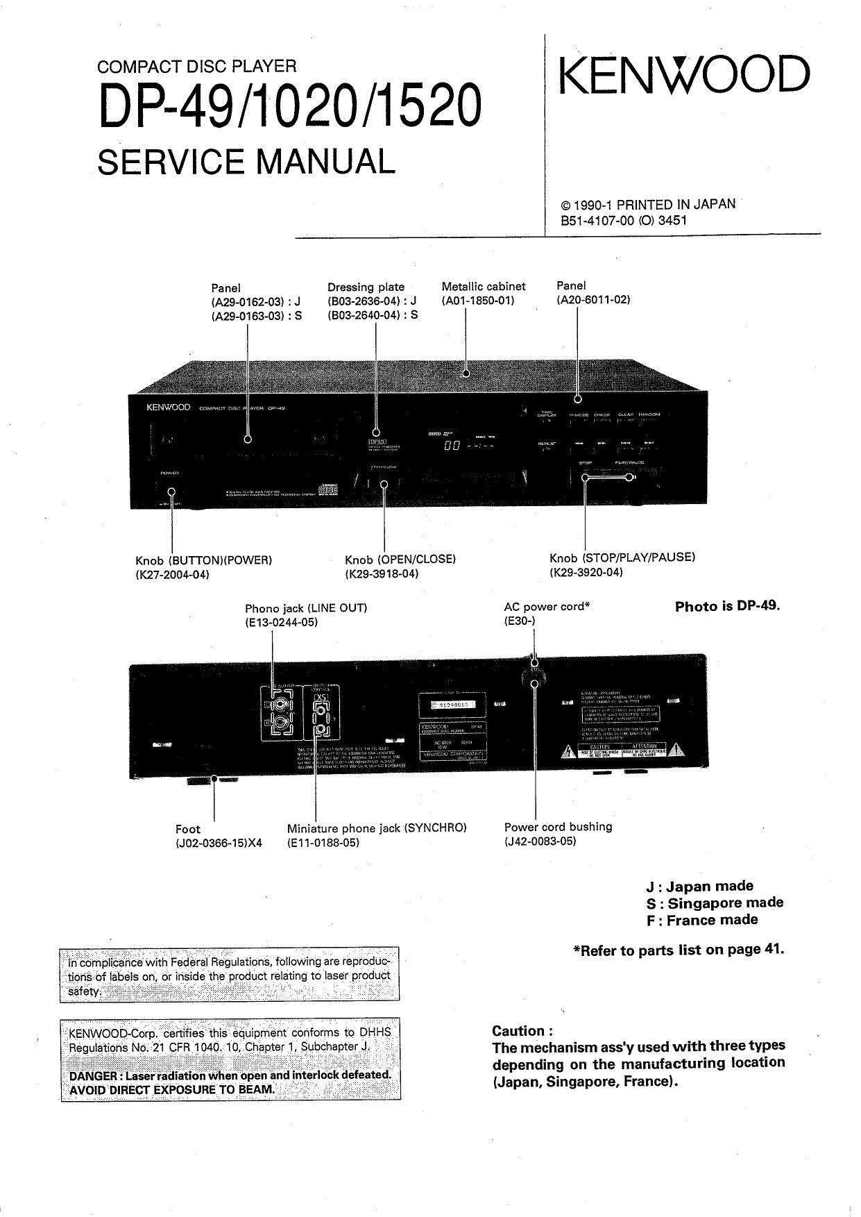
Panel Dressing plate Metallic cabinet Panel
(A29-0162-03I : J (BOB-26364) : J (A01~1850-O1I IA20-6011-02)
IA29-0163-03) : S (BOB-2640434) : S

KENV. (JOD v:

Knob (BUTTONMPOWER) Knob (OPEN/CLOSE) Knob ISTOP/PLAY/PAUSE)

IK27-2004-04) (K29-3918-04) (K29-3920-04I
Phone jack (LINE OUT) AC power cord* Photo is DP-49.
(E13-0244-05) (E30-I

Foot Miniature phone jack (SYNCHROI Power cord bushing
(J02~0366-15)X4 IE1 $018805) (J42-0083-05)

J : Japan made
6 : Singapore made
F : France made

*Refer to parts list on page 41.

Caution :

. . I The mechanism ass'y used with three types
DANGER : Lasenadamn when open an ' \ depending on the manufacturing location

9 AVOID DIRECT EXPOSURE To BEAM 3 V . (Japan, Slngapore, France).

Page 2

DP-49/ 1020/1520

CONTENTS

DISASSEMBLY FOR REPAIR
1. Removing the outside fittings ........ 4
2. Removing and installing the tray ..... 6
3. Removing the pickup (Japan made) ............. 8
3. Removing the pickup
(Singapore and France made) .......... 9
BLOCK DIAGRAM ..................................
CIRCUIT DESCRIPTION

1. Description of components
2. Test mode ...............................
3. Microprocessor : uPD75212ACW-185

MECHANISM OPERATION DESCRIPTION .......... 25

1. Tray OPEN/CLOSE operation ...................... 26
2. Pickup chassis UPIDOWN movement .

3. Gear installing position
ADJUSTMENT .......
VOLTAGE TABLE
PC BOARD .....................
SCHEMATIC DIAGRAM...

EXPLODED VIEW (MECHANISM)

:JAPAN MEDE .................................

EXPLODED VIEW (MECHANISM)


(X32-1610-XX: I04) ................ : SINGAPORE MADE ......................................... 38
4. RF AMP : CXA1081$ EXPLODED VIEW (MECHANISM)
(X32-1610-XX: IC1) ....................................... 16 : FRANCE MADE .............
5. Servo control : CXA1244S EXPLODED VIEW (UNIT)
(X32-1610-XX : ICZ) ....................................... 18 PARTS LIST .........................
6. Digital signal processor : CXD1167Q SPECIFICATIONS
(X32-1610-XX : IC3) ............ é .......................... 20 DP-49, DP-1020 ..
7. Custum IC: KASO1 (HIC) DP-1520 ..............
(X32-1610-XX : I09) .....
JAPAN MADE SINGAPORE MADE FRANCE MADE
DF-4s CONTROL UNIT x32-1510-10 (K,P) X32-1630-IO (K) -
X32-1610-21 (M)
X32-1610-71 (X)
MECHANISM ASS'Y X92-137005 X92-I400-05 (K) -
DP-1020 CONTROL UNIT X32-1610-11 (P) K32-1632-71(E,T) X32-1652-70 (E.T)
X32-1610-22 (M,Y)
X32-1610-72 (X)
MECHANISM ASS'Y X924370-05 X92-14oo-05 X92-1410-00
DP-1520 CONTROL UNIT X32-1610-12 (K) X32463041 (K) -
MECHANISM ASSY X92-1370-05 X92-I4oo-05 -
NOTE :

3models are written in this manual. Before using this manual, please check manufactur-
ing place and PC board ass'y number.
Control PC board ass'y (X32-) parts list (page 45)is written the parts for all of 3models.
Reler to comparision table in schematic diagram.

Page 28

DP-49/ 1020/ 1520

ADJUSTMENT

INPUT OUTPUT PLAYER ALI GNHENT
No. ITEN SETTING SETTING SETTING POINT ALIEN FOR FIG
Shortcircuit pins 0n the power from
TEST and turn the Oil to 0.3M, when
power on to enter the diffraction
the test mode. grating is correctly
Apply the sensor Press the llAlIIIAL S. aligned with the RF
section of the optical keyt»)to move the level of 1.5Vp-D
1 LASER POKER - power meter on the pickup outwards. - or more and (a)
pickup lensl Press the CHECK he the TB (servo open)
to check that the LD level 0! 1,5Vp'p
emits light. Then or more. the pickup
conIIr- that the is acceptable

display is" 03 '.

Connect a fretmency Press the STOP key. L2
2 V00 - counter to PLCK (TN) and confirm that (X32-I510) 4.3mm: (b)
(24510) the display is '01".

Press the REPEAT ke
Connect an oscilloscop to open the trayi

as follows. Load a disc and Symmetry between
TRACKING ERROR Test disc Cl'll: RP close the tray by TE BALANCE upper and lower
3 BALANCE . Type A (HZ-1610 CNT-l) pushing it by hand. VR2 patterns. (c)
CH2: TE Thempress the CHECK 032-1610) or DC=DiIL03V
(HZ-13) CN76) key. Confirm that

the display is'03".

Connect an oscilloscope

as follows. Press the PLAY
FOCUS ERROR Test disc CHI: RF key. Confirm that FE BALANCE
4 BALANCE Type 4 (xsznsiu cm-I) the display VRI Optimum eyepattetn (d)
CI-IZ: TB is" N5 '. (NH-1610)
(24610 ONT-E)
Test disc
Type 4 Connect a LPF to Cl Press the PLAY Two VTVNs should read
APDly signal of fin 2-3 to which connect key. Confirm that FOCUS GAIN the same Value.
5 FOCUS GAIN EflflllzJIJDInVrms to an oscilloscope the display TIRE lNDnans (6)
cm pin 2-3 or an AC voltmeter. is 65 '. (xsznslu)
032-1610) (xaz-mu)
Test disc
Type 4 Connect a LPF to CM Press the PLAY Two VTVNs should read
Apply signal of pin 5-6 to which connect keyi Confirm that TRACKING GAIN the same value,
6 TRACKING GAIN l.2kl|z.lNNmVrns to an oscilloscope the display VRA 100mllrns (e)
0N7 pin 5-6. or an AC voltmeter is"05 ' . (KSZ-ISIN)
(Hz-1610) (xaz-Isw)

(Note) Type 4 disc: SONY YDS-ls Test Disc or equivalent.
LPF: Around 41kohms+390ph or so.
Step l~6 are in Test Node.

(a) Laser Power (a) Focus Gain, Tracking Gain

Focus GAIN CN7 (9

0" " °~3'"W Two VTVMs should H 0
read the same value, 300 2 6

(MB (100mVrms) 100mV Q

(9

@

Optical power meter

TRACKING GAIN cm 6)
Two VTVMs should
read the same value. ©
one (100mVrmsl (9
G}
1.2kHz a 0
2,, 2-9.