Kenwood DNX 7000 EX Service Manual

This is the 106 pages manual for Kenwood DNX 7000 EX Service Manual.
Read or download the pdf for free. If you want to contribute, please mail your pdfs to info@audioservicemanuals.com.

Page: 1 / 106
left right
Kenwood DNX 7000 EX Service Manual

Extracted text from Kenwood DNX 7000 EX Service Manual (Ocr-read)


Page 1

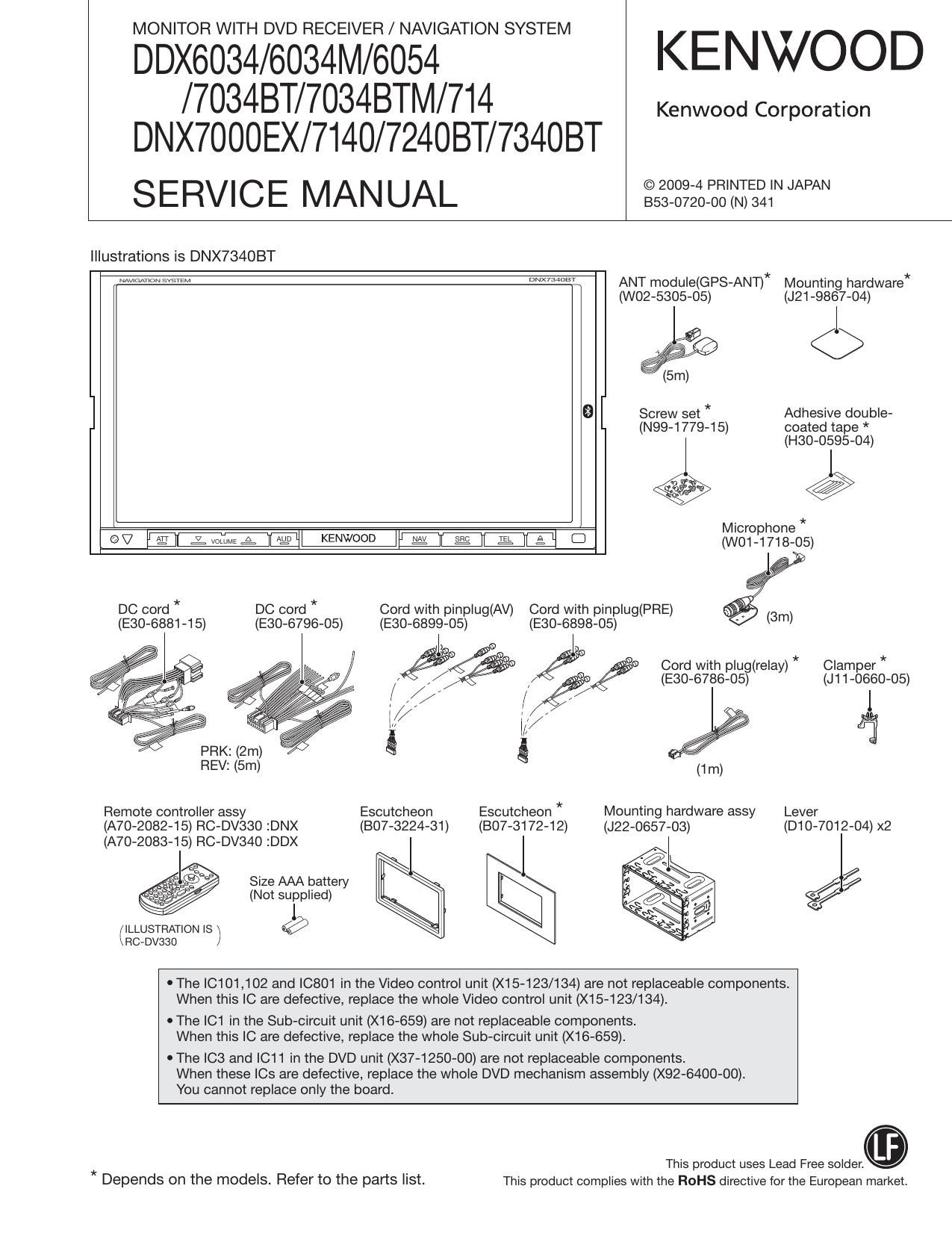
MONITOR WITH DVD RECEIVER / NAVIGATION SYSTEM

DDX6034/6034M/6054 KENWOOD
/7034BT/7034BTM/714 Kenwood Corporation
DNX7000EX/7140/724OBT/734OBT

SERVICE MANUAL -529gigt22'?NIEZINWN

Illustrations is DNX734OBT

WWWW WM ANT modu|e(GPS-ANT)* Mounting hardware*
(W02-5305-05) (J21-9867-04)

%

(5m)
9 Screw set * Adhesive double-
(N99-1779-15) coated tape *
l (H30-0595-04)

@@

Microphone*
«W W7 LIME: AMI KENWOOD Im E g a C1 (W01-1718-05)
4

DC cord * DC cord * Cord with pinplug(AV) Cord with pinplug(PRE)
(E30-6881-15) (E30-6796-05) (E30-6899-05) (E30-6898-05)


i y 9
@ Cord with plug(relay) * Clamper *
" // ,// / (E30-6786-05) (J11-0660-05)
i ; ,// / // I

I /.
g/ Ir/ fi
(1m)
Remote controller assy Escutcheon Escutcheon * Mounting hardware assy Lever
(A70-2082-15) RC-DV33O :DNX (807-3224-31) (BO7-3172-12) (J22-0657-03) (D10-7012-04) x2
(A70-2083-15) RC-DV34O :DDX
Size AAA battery
(Not supplied) @g/
(ILLUSTRATION Is \ @
achvsao /

' The |C101,102 and |0801 in the Video control unit (X15-123/134) are not replaceable components.
When this IC are defective, replace the whole Video control unit (X15-123/134).

I The |C1 in the Sub-circuit unit (X16-659) are not replaceable components.
When this IC are defective, replace the whole Sub-circuit unit (X16-659).

0 The ICS and |C11 in the DVD unit (X37-1250-00) are not replaceable components.
When these le are defective, replace the whole DVD mechanism assembly (X92-6400-00).

You cannot replace only the board.
This product uses Lead Free solder.

* Depends on the models. Refer to the parts list. This product complies with the ROHS directive for the European market.

Page 9

DDX6034/6034M/6054/7034BT/7034BTMN 14

DNX7000EX/7 1 40/ 7240 BT/ 7340 BT
MICROCOMPUTERS TERMINAL DESCRIPTION

Pin No. Pin Name l/O Application Tfiggréue Processing/Operation/Description
22 XIN
23 VCC1
24 NMI
25 ACCiDET I ACC detection H: ACC reduced voltage detection
26 BU,DET I Backup power detection H: Backup power reduced voltage detection
27 RiCLK I Clock input from RDS decoder
28 NC I Not used. Input is fixed to Hi Not used. Input is fixed to Hi
29 PisTART O ON/OFF control of X1 SiDC-DC
3O PGOOD I Power supply error detection H: Error, L: Normal
_ (PWM output synchronized with HSY is under
31 INV7PWM O Brightness control of LCD (PWM output) .
reVIew)
32 PARKING I Parking detection (For all destinations) H: Parking is detected, L: Car is running
F t | fX15 DC-DC IC
33 POWERiPWM o requency co m D * * Duty50%
(CLK output)
34 PON O ON/OFF control of SW power supply H: ON, L: OFF
35 BEEP O BEEP PWM output
36 AV|N3,SW O iPod/AVinS switching HIAVIn3, L:iPod in
Terminal used to detect if the product destina- , _ _
37 TYPEiSD I (1) H: SD slot IS needed, L: SD slot is not needed
tion needs SD slot or not.
Output is fixed to L in the product whose desti-
38 TV,MC,DATA 0 Data output to TV u-com _
nation does not need TV.
39 VCC1
_ Output is fixed to L in the product whose desti-
40 TvisciDATA I Data Input from TV u-com
nation does not need TV.
41 V88
_ _ _ Output is fixed to L in the product whose desti-
42 TV7BPiCLK 0 Communication clock With TV u-com .
nation does not need TV.
43 NC (BUSY) 0 NC (FLASH re-writing)
44 TUNisDA I/O Communication data with tuner
45 TUN,SCL 0 Communication clock with tuner
Output is fixed to L in the product whose desti-
46 TV,MC,REQ 0 Request to TV u-com .
nation does not need TV.
Ot t'f'dtL'th dth dt'-
47 TV,SC,CON 0 Request to boot up TV u-com uApu IS ixe O In e pro uc W ose es I
nation does not need TV.
48 TV JUDGE I Determ'nation of TV BOX if it is old or new H: BOX is Old L: BOX IS new
I (Fixed to Hi for destinations K and M)
49 KABiDET I Sirius connection detection
50 KABiPON O ON/OFF of SAT power supply
51 ANT7CON 0 Power antenna control H: UP, L: DOWN
52 PiCON O P-CON control L: STANDBY, POWER OFF, H: EXCEPT
53 REVERSE l Reverse detection L: Reverse is detected, H: Normal
54 NC (EPM) 0 Not used. Output is fixed to L Not used. Output is fixed to L.
NC/CODEC,CS/ _
55 O CODEC CS L: Active
CODEciCS
55 NC/CODECiCS/NC 0 Output is fixed to L Not used. Output is fixed to L
56 INV,SYNC O Inverter frequency control (Pulse output) DUTY5%

Page 24

DDX6034/6034M/6054fl 034BT/7034BTMN 14
DNX7000EX/7140/724OBT/734OBT

24

TEST MODE

2.4.10. AV IF

I The settings in the Test mode are described in Table 2.4.8.
(The settings of items which are not listed in the table are
as usual.)

Settings
AV-IN Interruption ON
R-CAM Interruption ON
NAV Interruption SP Setting Front ALL

I An interruption occurs in R-CAM detection while in nor-
mal detection operation.

I V-IN (R-CAM) mirror mode shall be switched with Tenkey
#3 on the remote controller.

2.4.11. Screen adjustment

I Except for Bright during Illumi OFF, the default shall be
Center. (Default of Bright during Illumi OFF is MAX.)

I One click operation will perform changes in the following
order: MIN <-> Center <-> MAX.

I Transfer to the Screen adjustment screen with Tenkey6
on the remote controller.

2.4.12. DC Offset
I DO Offset detection status (normal/error) clear
By pressing the [DC Offset Clear] key in the Service
screen, clear DC Offset detection information.
I DO Offset detection information is displayed on the Infor-
mation screen/Service screen.
I In the Test mode, even if DC Offset is detected, it is not
written into the nonvolatile memory.
However, the detection operation shall be carried out
and when the DC Offset is detected, the Protect shall be
displayed and it becomes all CH Mute operation.
I Volume setting can be changed to the following settings
by pressing Tenkey 2 on the remote controller.
Source : DVD
Assigned DISC : KTD-02A
Assigned Track : 15 (20Hz, OdB)
Assigned VOL : 26 Step

2.4.13. Panel Mechanism
The Touch operation is operative even in the Full Open state
of the Tilt mechanism.

2.4.14. Clear the contents in the nonvolatile
memory (E2PROM etc.)
I Clear the contents in the nonvolatile memory which must
not remain at the time of shipment.
Clear the contents in the nonvolatile memory with the
[SRC] key, the [AUD] key, and the [Reset] key.
Clear OK : Change the key illumi to blue.
Clear NG : Change the key illumi to red.
In clearing operation : Change the key illumi to white.
I The following information is cleared:
DC Offset information / Memory function/ Retailer mode
information / Service information
I If a jig is connected and the region is written in, the fol-
lowing information shall be cleared.
Serial No. / Security code / Touch correction / LCD ad-
justment value / Mechanism position adjustment value
DC Offset informatio / Memory function / Retailer mode
information / Service information / Illumi adjustment

Notes:
When replacing the following elements by the service staff
members, perform adjustment again in the Test mode since
the following data is cleared.
When replacing E2PROM (X15: ICZOS),
Security code / Touch correction Mechanism position
adjustment value
DC Offset information / Memory function / Retailer mode
information / Service information
When replacing Flash Memory (X35: ICZOO) for M-Star,
General LCD adjustment (including the flicker adjust-
ment) Illumi adjustment
When replacing F-RAM (X15: ICBOO) for Magnum,
Input serial No.

2.4.14. Version Check
I While in the Test mode, connecting a USB containing a
specific file will compare it with information described in
each version and file to judge whether it is OK. or N.G.
Select black for the background color until Check OK/
NC" is displayed.
Modify the background color to blue at the same time
as Check OK is displayed.
Modify the background color to red at the same time