Kenwood DNX 6140 Service Manual

This is the 72 pages manual for Kenwood DNX 6140 Service Manual.
Read or download the pdf for free. If you want to contribute, please mail your pdfs to info@audioservicemanuals.com.

Page: 1 / 72
left right
Kenwood DNX 6140 Service Manual

Extracted text from Kenwood DNX 6140 Service Manual (Ocr-read)


Page 1

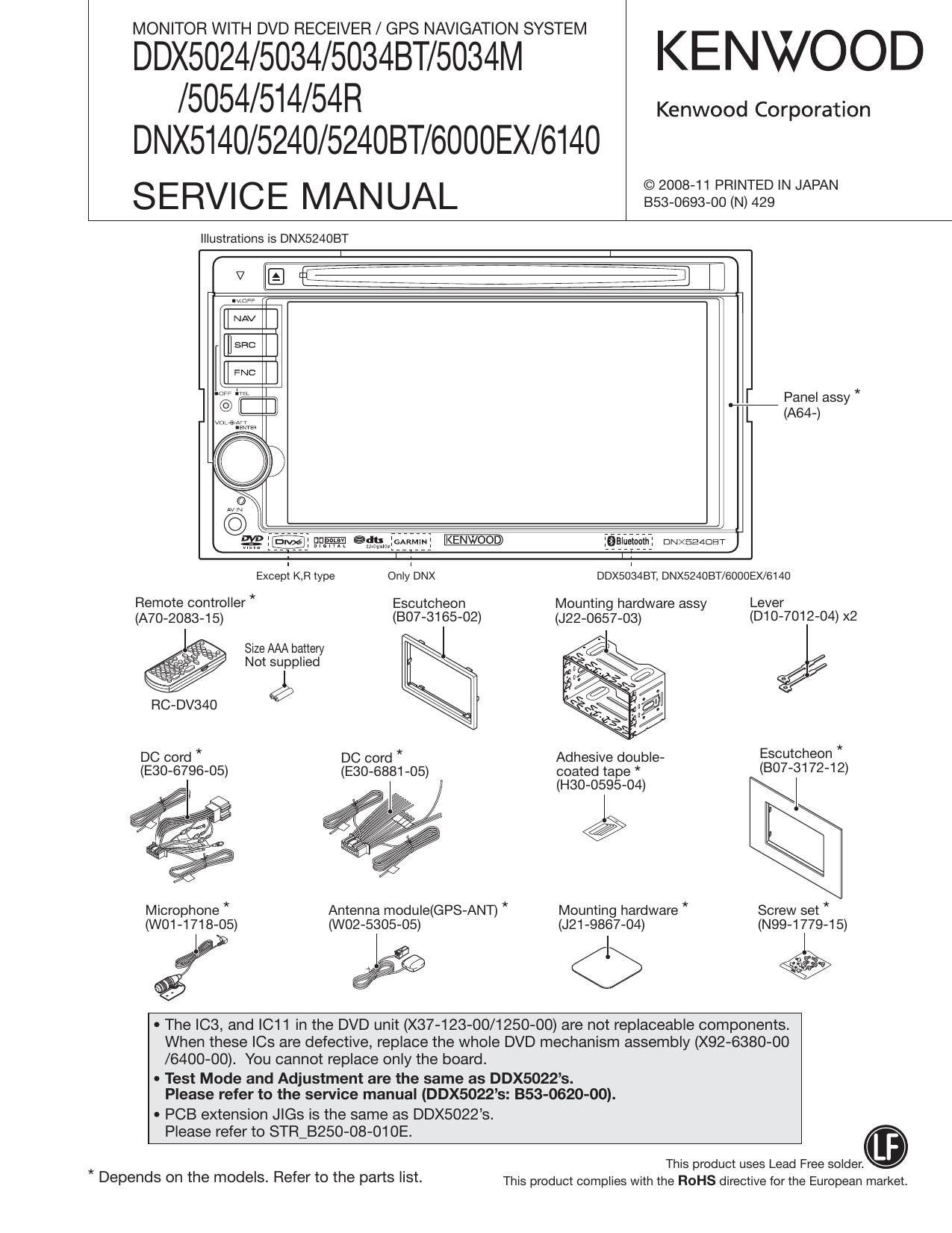
MONITOR WITH DVD RECEIVER / GPS NAVIGATION SYSTEM

DDX5024/5034/5034BT/5034M KENWOOD
/5054/514/54R

DNX5140/5240/524OBT/6000EX/6140
SERVICE MANUAL IIIIIIIIIIIIWN

Kenwood Corporation

Illustrations is DNX524OBT

[I NAV

EI

FNC

] E:E

WM?

:Balueiaam: DNXEEADET

ExcepI KB type OnlleNX DDXSOISABT, DNX524OBT/6000EX/6140
Remote controller * Escutcheon Mounting hardware assy Lever
(A70-2083-15) (BO7-3165-02) (J22-0657-03) (D10 7012- 04)x
Size AAA battery I -

a / Not supplied

l
RC-DV340 9
DC cord * DC cord * Adhesive double- Escutcheon *
(E30-6796-05) (E30-6881-05) coated tape * (807-31 72-1 2)

(H30-0595»04) I

Microphone * Antenna module(GPS-ANT) * Mounting hardware * Screw set *
(WO1-1718-05) (W02-5305-05) (J21 -9867-04) (N99-1779-15)

EEE <1> E

0 The IC3, and |C11 in the DVD unit (X37-123-00/1250-00) are not replaceable components.
When these le are defective, replace the whole DVD mechanism assembly (X92-6380-00
/6400-OO). You cannot replace only the board.

- Test Mode and Adjustment are the same as DDX5022s.
Please refer to the service manual (DDX5022s: 353-0620-00).

- PCB extension Jle is the same as DDX5022s.

Please refer to STR_B250-08-01 OE.
This product uses Lead Free solder.

* .
Depends on the mOdeIS- Refer to the parts I'St- This product complies with the ROHS directive for the European market.

Page 14

DDX5024/5034/5034BT/5034M/5054/514/54R
DNX5140/5240/5240BT/6000EX/6140
MICROCOMPUTERS TERMINAL DESCRIPTION

Destination Settings
MODEL Destination TYPE2 (94) TYPE1 (92) TYPEO (122) TYPE3 (55)
K o 0
E
M
V/X
R

With BT
Without BT

TYPEO is AD input
:k Refer to the next table (TYPEO Setup Voltage)
E of TYPEO should be same as E2 of TYPEO

TYPE4 (75)
5VPRE 1
2VPRE O
TYPEO Setup Voltage
Destination _ u-oom setup value Pull down resistor Pull up resistor
min Mid point voltage max
K 0.00 0.00 0.41 10
E 0.42 0.83 1.23 3.3 10
M 1.24 1.65 2.06 10 10
V/X 2.07 2.48 2.88 30 10
R 2.89 3.30 3.30 - 10
ASEL Set Up
MAIN
ASEL171 (99) ASEL172 (98)
BE 0 0
(TV) 0 1 Models for destination K and R do not have TV
IPOD 1 0
KAB or ET 1 1 KAB except for E destination with BT
SUB
ASEL271 (97) ASEL272 (96)
BE 0 0
(TV) 0 1 Models for destination K and R do not have TV
IPOD 1 0
- 1 1

In the model without TV, ASEL272 output is fixed to L"
14