Kenwood DNX 5240 BT Service Manual

This is the 72 pages manual for Kenwood DNX 5240 BT Service Manual.
Read or download the pdf for free. If you want to contribute, please mail your pdfs to info@audioservicemanuals.com.

Page: 1 / 72
left right
Kenwood DNX 5240 BT Service Manual

Extracted text from Kenwood DNX 5240 BT Service Manual (Ocr-read)


Page 1

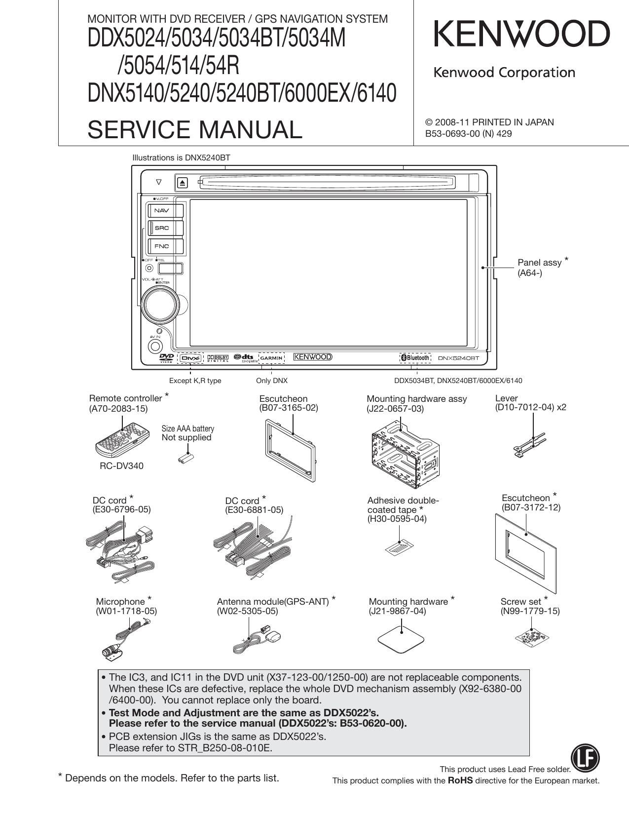
MONITOR WITH DVD RECEIVER / GPS NAVIGATION SYSTEM

DDX5024/5034/5034BT/5034M KENWOOD
/5054/514/54R

DNX5140/5240/524OBT/6000EX/6140
SERVICE MANUAL IIIIIIIIIIIIWN

Kenwood Corporation

Illustrations is DNX524OBT

[I NAV

EI

FNC

] E:E

WM?

:Balueiaam: DNXEEADET

ExcepI KB type OnlleNX DDXSOISABT, DNX524OBT/6000EX/6140
Remote controller * Escutcheon Mounting hardware assy Lever
(A70-2083-15) (BO7-3165-02) (J22-0657-03) (D10 7012- 04)x
Size AAA battery I -

a / Not supplied

l
RC-DV340 9
DC cord * DC cord * Adhesive double- Escutcheon *
(E30-6796-05) (E30-6881-05) coated tape * (807-31 72-1 2)

(H30-0595»04) I

Microphone * Antenna module(GPS-ANT) * Mounting hardware * Screw set *
(WO1-1718-05) (W02-5305-05) (J21 -9867-04) (N99-1779-15)

EEE <1> E

0 The IC3, and |C11 in the DVD unit (X37-123-00/1250-00) are not replaceable components.
When these le are defective, replace the whole DVD mechanism assembly (X92-6380-00
/6400-OO). You cannot replace only the board.

- Test Mode and Adjustment are the same as DDX5022s.
Please refer to the service manual (DDX5022s: 353-0620-00).

- PCB extension Jle is the same as DDX5022s.

Please refer to STR_B250-08-01 OE.
This product uses Lead Free solder.

* .
Depends on the mOdeIS- Refer to the parts I'St- This product complies with the ROHS directive for the European market.

Page 13

DDX5024/5034/5034BT/5034M/5054/514/54R

DNX5140/5240/5240BT/6000 EX/6140
MICROCOMPUTERS TERMINAL DESCRIPTION

Pin No. Pin Name l/O Application Processing / Operation / Description
112 SlRiDET l Sirius connection detection
113 SlRiPON 0 SAT power supply ON/OFF
114 NC 0
115 TVJJUDGE 1 Determination of TV7BOX if it is old or new H: Old, L: New
115 NC 0 Output from model without TV is fixed to L
116 ANT,CON 0 Power antenna control H: UP, L: DOWN
117 P,CON O P-CON control L: STANDBY, POWER OFF, H: EXCEPT
118 ILLUMI | Illumination detection L: ON, H: OFF
1 19~121 NC 0
122 TYPEO | Destination settings Refer to Destination settings"
123 KEYS | Key3 input Refer to KEYS matrix"
124 TUNilFC | F/E IFC input H: Station found, L: Station not found
125 TUN,SMET | S meter Input
126 FLNOISE | FM noise input
127 FLAFsiH |/O Time constant switching when F/E noise is detected
128,129 NC 0
130 VSS
131 NC 0
132 VCC1
133,134 NC I Not used (input)
135 VlLLiDET l Variable illumination identification terminal L: F3, H: F4
136 VCOM I For VCOM level automatic adjustment
137 XiDATA l Touch data input
138 YiDATA 1 Touch data input
Normal: 1.6V
139 LINEiMUTE | LlNE-MUTE input detection TEL MUTE: 1V or lower
NAVI MUTE: 2.5V or higher
140 AVSS
141 PWIC,DC,DET 1 SP output DC offset detection L: When detected
142 VFIEF
143 AVCC
144 EVOL,SCL/EVOL,SCL 0 Communication clock with E-VOL
144 EVOL,SCL/E2P,SCL 0 Communication clock with E2P

13