Kenwood DNX 5180 Service Manual

This is the 122 pages manual for Kenwood DNX 5180 Service Manual.
Read or download the pdf for free. If you want to contribute, please mail your pdfs to info@audioservicemanuals.com.

Page: 1 / 122
left right
Kenwood DNX 5180 Service Manual

Extracted text from Kenwood DNX 5180 Service Manual (Ocr-read)


Page 1

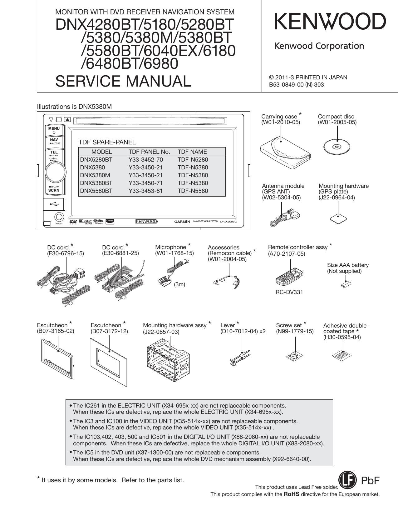
MONITOR WITH DVD RECEIVER NAVIGATION SYSTEM

DNX42808T/5180/52808T
/5380/5380M/53808T
/558OBT/6040EX/6180

KENWOOD

Kenwood Corporation

/64BOBT/6980
SERVICE MANUAL

© 2011-3 PRINTED IN JAPAN
B53-0849-00 (N) 303

Illustrations is DNX5380M


7 7 7 7 7 Carrying case" Compact disc
V D E' Le 7 7 7 7 7 7 7ij (w01-2010-05) (wo1-2005-05)
MENU \ / l
d) 7
3153's TDF SPARE-PANEL ©
2 MODEL TDF PANEL No. TDF NAME
DNX52803T Y33-3452-70 TDF-N5280
] \ DNX5380 Y33-3450-21 TDF-N5380
I DNX5380M Y33-3450-21 TDF-N5380
DNX5SSOBT 333450-71 TDF-N5380 Antenna module Mounting hardware
DNX55803T Y33-3453-81 TDF-N5580 (GPS ANT) (GPS plate)
(W02-5304-05) (J22-0964-04)
/ \ ?$
3 W .22 "annals; 13:. mm mm: O
I I
DC cord * DC cord * Microphone * Accessories Remote controller assy *

(E30-6796-1 5) (E30-6881-25)

(WO1-1768-15)

Escutcheon *
(807-3172-12)

Escutcheon *

(807-3165-02) (J22-0657-03)

Mounting hardware assy *

(Remocon cable)

(A70-2107-05)
(WO1-2004-05)

Size AAA battery

(Not supplied)

2% 1
@
RC-DV331

Lever * Screw set * Adhesive double-

(D10-7012-04) x2 (N99-1779-15) coated tape *

I (H30-0595-04)

®

.

OThe |C261 in the ELECTRIC UNIT (X34-695x-xx) are not replaceable components.
When these |Cs are defective, replace the whole ELECTRIC UNIT (X34-695x-xx).

'The |C3 and |C1 00 in the VIDEO UNIT (X35-514x-xx) are not replaceable components
When these le are defective, replace the whole VIDEO UNIT (X35-514x-xx) .

'The |C103,402, 403, 500 and ICSO1 in the DIGITAL |/O UNIT (X88-2080-xx) are not replaceable
components. When these |Cs are defective, replace the whole DIGITAL I/O UNIT (X88-2080-xx).

'The |C5 in the DVD unit (X37-1300-00) are not replaceable components.
When these |Cs are defective, replace the whole DVD mechanism assembly (X92-6640-00).

* It uses it by some models. Refer to the parts list.

This product uses Lead Free semen.

This product complies with the ROHS directive for the European market.

Page 29

DNX4280BT/5180/5280BT/5380/5380M

/538OBT/5580BT/6040EX/6180/64803T/6980

TEST MODE

Simple DSP Model Model without DSP
Space Enhancer OFF -
Line Mute ON ON
DSP ON/OFF ON -
Preout switching - Rear

Table 2.3.8-A Test mode defaults

The key operation in the Test mode is described in Table
2.3.8-B. (The settings of items which are not listed in the
table are as usual.)

Simple DSP Model Model without DSP
With one click With one click
Balance _ _
LefteCentereRight LefteCentereRight
With one click With one click
Fader
FronteCentereRear FronteCentereRear
With one click With one click
Xover FREQ
MlN<->MAX MlN<->MAX
EQ (Tone) Level With one click With one click
MINeOeMAX MlNeOeMAX
Key is inside the Audio
DSP ON/OFF -
Setup screen

Table 2.4.8-B Test mode key operation

2.3.8 AV IF
The settings in the Test mode are described in Table 2.3.9.
(The settings of items which are not listed in the table are as

usual.)

Settings
R-CAM Interruption ON
NAV lnterruption SP Setting Front ALL

Table 2.3.9 AV IF setting

2.3.9 Screen adjustment

Except for Bright during lllumi OFE the default shall be Cen-
ter. (Default of Bright during lllumi OFF is MAX.)

One click operation will perform changes in the following
order: MIN <-> Center <-> MAX.

Transfer to the Screen adjustment screen with TenkeyS on
the remote controller.

Canceling of the Screen adjustment screen is performed
with Tenkey6 of the remote controller.

2.3.10 DC Offset
11 Visual Mid/ Entry model maintains the DC Offset detec-
tion information (detection log) in the nonvolatile memory.

Check method of the DC Offset detection information
Display the DC Offset detection information on the Informa»
tion screen/ Service screen.

Clearing method of the DC Offset detection information
By pressing the [DC Offset Clear] key in the Service screen,
clear DC Offset detection information.

Operation during the test mode

Perform DC Offset detection operation, and display Protect
and perform all CH Mute when DC Offset is detected.
However, only during the test mode, do not update the DC
Offset detection information even if the DC Offset is detect»
ed. (Do not write to the nonvolatile memory.)

2.3.11 Panel mechanism
Make the touch operation possible even when the panel
mechanism is in Full Open status.

2.3.12 Clearing of data in nonvolatile memory
Clear the contents of the nonvolatile memories (E2PROM,
etc.) that need to be initialized at the shipment.

Operation procedure
Clear the contents of the nonvolatile memory with one of

the following operations.

(D Start the system by pressing [Reset] key while pressing
the following keys.
Mid : MENU + AUD
Entry : MENU + A'l'l'

(2) Input [8] a [m] a [9] using the remote controller (SW:
AUD) while in standby source.

Display specification
Notify the status of clearing / cleared of the contents of the

nonvolatile memory using the color of the key illumi.

Also, notify the end of clearing of memory contents using
the pop-up display.

For color and specification of the pop-up, refer to the Table
2.3.12. (Pop»up cannot be erased after the pop-up is dis-
played. Turn the power OFF.)

_ _ Pop-up display
Key lllumi
Status Background
color Text
color
Clear completed Blue OK Blue
Clear completed
_ _ Green NG Green
(Serial No. IS not written)
Clear failed Red NG Red
Clearing White - -

Table 2.3.12 Display during the nonvolatile memon/ contents clear

29