Kenwood DNX 5120 Service Manual

This is the 86 pages manual for Kenwood DNX 5120 Service Manual.
Read or download the pdf for free. If you want to contribute, please mail your pdfs to info@audioservicemanuals.com.

Page: 1 / 86
left right
Kenwood DNX 5120 Service Manual

Extracted text from Kenwood DNX 5120 Service Manual (Ocr-read)


Page 1

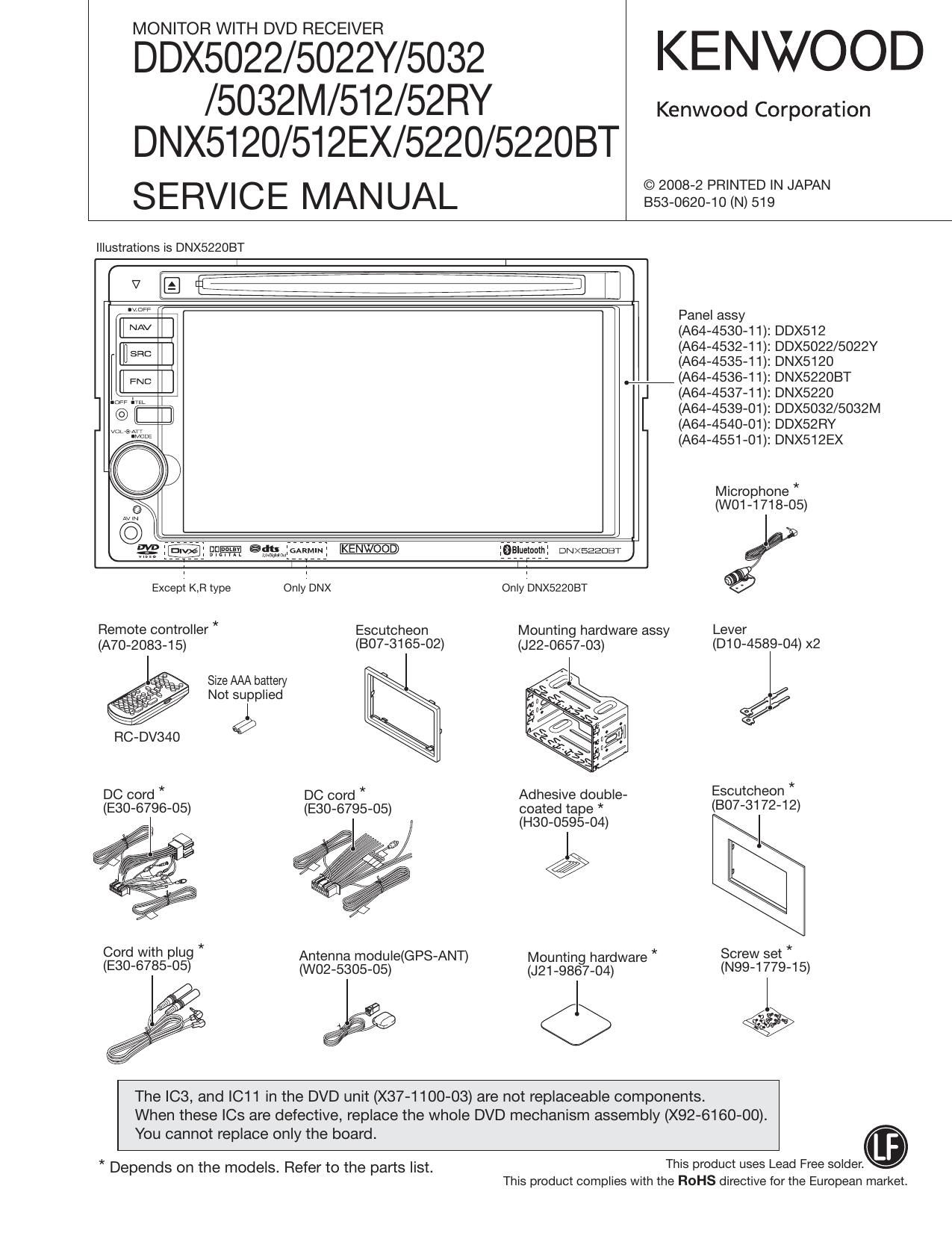
MONITOR WITH DVD RECEIVER

DDX5022/5022Y/5032 KENWOOD

/5032M/512/52RY Kenwood Corporation
DNX5I20/512EX/5220/52208T

SERVICE MANUAL sszNgzgifiz'tiiegNNNN

Illustrations is DNX522OBT

N [E fleeiiii i 7 iiiifij 7
"W Panel assy
[i AV l (AM-453041): DDX512
EH SEC (AM-453241): DDX5022/5022Y
(A64-4535-11): DNX5120
we (AM-453641): DNX5220BT
(A64-4537-11): DNX5220

n@ i[ ii (A64-4539»01): DDX5032/5032M
(A64-4540»01): DDX52RY
(A64-4551»01): DNX512EX

Microphone *
(W01-1718-05)

Jgp ammiftwil 9915211101111 owxeaaom)
1 1
Except K,Fl type Only'DNX Only'DNX5220BT

Remote controller * Escutcheon Mounting hardware assy Lever
(A70-2083-15) (BO7-3165-02) (J22-0657-03) (D10-4589-04) x2

Size AAA battery

Not sulpplied %/

RC-DV340 W

DC cord * DC cord * Adhesive double- Escutcheon *

(E30-6796-05) (E30-6795-05) coated tape * (307-3172-12)
, (H30-0595-04) J

Cord with plug * Antenna module(GPS-ANT) Mountin hardware * Screw set *
(E30-6785-05) (W02-5305-05) (J21_98§7_04) (N99-1779-15)

ee <5 ,.

The IC3, and IC11 in the DVD unit (X37-1100-03) are not replaceable components.
When these le are defective, replace the whole DVD mechanism assembly (X92-6160-00).

You cannot replace only the board.
This product uses Lead Free solder.

* Depends on the models. Refer to the parts list.
This product complies with the ROHS directive for the European market.

Page 18

DDX5022/5022Y/5032/5032M/5l2/52RY
DNX5120/512EX/5220/52208T

18

TEST MODE

3.4 Serial No. Entry screen
Enter the serial code of each set from this screen.
The Serial No. Entry screen is shown in Figure 3.4.

3.5.1 DVS-8000 Adjustment screen
This is to display DVS-8000 Servo Adjustment screen.
Refer to the Mechanism Specification for the detail setup.

Serial Number Input

Serial Number Input

III :9
"III
lIl

Figure 3.4 Serial No. Entry screen

Key Specification
0~9 : 10key used to enter the serial No.
Clear : Clear the serial No. being input.
Cancel: Transfer to Service screen
Enter : Start entering the serial No.
(When the entry is successfully completed, the
Write OK" is shown. When the entry is not suc-
cessfully completed, the Write NG" is shown)
When the Write OK" is shown, use this key to
transfer to the Service screen.
If the Write NG" is shown, transfer to the Test
mode again and repeat the entry from the first

step.

3.5 DVD Service Information screen

This screen is to show DVS-8000 sen/ice information. This
screen is also used to transfer to DVS-8000 Adjustment
screen.

The DVD Service screen is shown in Figure 3.5.

DVSVSODO Service Information

DVSVSDOO Adjust

DVSVBOOO Service Information
"mm...
um...
«mm...

"W' "nun-u
mm- E> ..........
.m... ..........
"mw' uncut-ta
twww "nun-u
twww "nun-u

Figure 3.5 DVD Sen/ice Information screen

Key Specification
DVS-8000 Adjust: Transfer to DVS-SOOO Adjustment screen

Next :Transfer to next DVS-8000 Service In-
formation screen.
Return : Transfer to Test Mode Main screen

ovs-Boon Adjust

®orset Cancel

@Facus Hejgm

ovs-suao Adjust ovs»suoo Adjust

Adjust OK/NG

w

Figure 3.5.1 DVS-8000 Adjustment screen

Key Specification
Offset Cancel: Adjust the offset cancel.

Inner Limit : Adjustment of inner circumference limit
Focus Height : Adjustment of focus height
Adjust Start : Start of adjustment
Return (the First screen) : Transfer to Test Mode Main
screen.
Cancel/Return : Transfer to DVS-8000 Adjust screen (Ini-
tial screen).

3.6 Tuner Mute Level screen
Adjust the Mute Level stored in the E2PROM of the Tuner F/E.
The Tuner Mute Level Setup screen is shown in Figure 3.6.

Tuner Mule Level Tuner Mute Level

- :5 wreck/us
Iwme

Figure 3.6 Tuner Mute Level Setting screen

Key Specification
UP : Mute Level Up
DW : Mute Level Down
lWrite: Press and hold (for 1 seconds or longer) to make
the entry in the E2PROM.
Return : Transfer to Service screen.

* Adjust the Tuner Mute Level under the following condi-
tions. Under the other conditions than the followings, the
Tuner Mute Level cannot be adjusted if the Tuner Mute
Level Setup screen is shown.

The frequency shall have to be set before transferring to
the Setup screen.

Audio Source : Tuner

LOUD : OFF

Volume : StepSO

Page 19

DDX5022/5022Y/5032/5032M/5l 2/52RY

DNX5I20/512EX/5220/52208T

TEST MODE

Frequency : Default value of the set
Note that the frequency remains unchanged after exiting

from the Setup screen at the completion of the setup.

3.7 Direct Select screen

Transfer to the Direct Select screen. Source Direct screen
shall have the screen that has 9 keys. Audio Control/Setup
shall be done in the same manner as in the normal screen
transfer.

3.8 Touch screen

Fine-tune the variations of touch feeling in of each set.
Touch 4 markers one by one, and the adjustment is com-
pleted when the Write OK is shown on the screen.

If the Write NG" is shown, transfer to the Test mode again
to re-start the adjustment from the first step.

The Touch Adjustment screen is shown in Figure 3.8.

Touch Adjust Touch Adjust
trpoinl being input eroinl being input
Ci) Wite OK/NG

arpoint being input Arpoinl being input

+i~ a}

Figure 3.8 TOUCH screen

Key Specification

Cancel: When the Cancel button is pressed while enter-
ing the 1st point, the system transfers to the Test
Mode Main screen.
When the Cancel button is pressed while enter-
ing the other point than the 2nd point, the system
transfers to the status to enter the 1st point.

Return : Transfer to Test Mode Main screen

3.9 HPOSI screen

Adjust horizontal position of each screen.

The screen shall be transferred like; Graphic->NAVI.
Graphic and NAVl of DNX are used in the adjustment of Dot
FREQ/Phase. The Adjustment screen is shown in Figure 3.9.

HPOSlAdjust
Gap,
(NAV') HPOSI
Stepvaiue
Dot FREQ C9
stepvaiue

Dot Phase
Step value

Figure 3.9 HPOSI screen

HPOSI Adjust

HPOSI OK/NG

Key Specification

Next : Transfer to the next HPOSI Adjustment screen.
When the screen is NAVI, the screen starts writing
in the E2PROM.

<< : Screen toward the left.

>> : Screen toward the right.

Cancel: Transfer to Test Mode Main screen

Return : Transfer to Test Mode Main screen

If HPOSI NG (E2PROM Write N6) is shown, transfer to the
Test Mode again to start over the adjustment.

3.10 iPod screen
Check communication for iPod authentication.
The iPod screen is shown in Figure 3.10.

iPod Check iPod Check

iPod OK/NG

c>

Figure 3.10 iPod screen

Key Specification
iPod Check :Start checking communication for iPod
authentication.
Cancel, Return: Transfer to Test Mode Main screen

19

Page 82

DDX5022/5022Y/5032/5032M/512/52RY
DNX5120/512EX/5220/522OBT
PARTS LIST

DAUGHTER UNIT (X89-3062-70)

A N . . Desti- A N . . Desti-
Ref. No. 3 iv Parts No. Description nation Ref. No. 3 iv Parts No. Description nation
R13 RK73G82A151J CHIP R 150 J 1/10W E3E4 96 18 X94-2080-00 ROLLER ASSY
R14 RK73G82A431J CHIP R 430 J 1/10W E3E4 98 2A X94-2060-00 TRAVERSE ASSY (PICKUPSPINDLE)
R15 RK73G82A270J CHIP R 27 J 1/10W E3E4 VM1 2A X94-2070-00 MOTOR ASSY (LOADING)
R17 RK73G82A431J CHIP R 430 J 1/10W E3E4
D1 iMSA-6801-E SURGE ABSORBER E3E4
Q1 28C3357-A TRANSISTOR E3E4
DVD MECHANISM ASSY (X92-6160-00) (DVS-8020V)
1 1A A10-5331-51 CHASSIS
2 28 A10-5332-51 CHASSIS
3 1A A10-5333-31 CHASSIS
4 3A >I< A10»5460-02 CHASSIS
7 18 D10-4918-22 ARM
8 18 D10»4919-22 ARM
9 18 D10-4920-02 LB/ER
10 18 D10-4921-02 LB/ER
12 28 D10-4922~12 SLIDER
13 2A >I< D10-7011-02 ARM
14 28 D10-4924-13 ARM
15 28 D10-4925~12 ARM
25 28 >I< D10-4973-D4 SLIDER ASSY
27 2A D10»4945-04 LB/ER
28 28 D12-0639-02 CAM
31 28 D13-2402-D4 GEAR
32 28 D13-2403-04 GEAR
33 28 D13-2404-04 GEAR
34 28 D13-2405-04 GEAR
35 28 D13-2406-04 GEAR
36 28 D13-2407-04 GEAR
40 2A D13-2413-04 GEAR
41 2A D13A2415-04 GEAR
42 2A D13-2416-D4 GEAR
43 18 D14-1013-14 ROLLER
53 18 D21 -2487-24 SHAFI'
54 2A >I< D39-0275-05 DAMPER
55 2A >I< D39-0276-05 DAMPER
60 3A FOB-282523 SHEET
65 28 G01-3298-04 EXTENSION SPRING
66 18 G01-3299-04 EXTENSION SPRING
67 2A G01-3300-14 TORSION COIL SPRING
68 28 601-4601-04 EXTENSION SPRING
69 18 G01-4602-04 EXTENSION SPRING
70 18 G014604-04 TORSION COIL SPRING
74 28 601-4609-14 TORSION COIL SPRING
75 18 * G02-1564-03 FLAT SPRING
79 2A >I< J22-0475-21 MOUNTING HARDWARE
BO 38 >I< J22-0636-01 MOUNTING HARDWARE
A 1A NOB-638205 MACHINE SCREW (M1 .7X2.0)
8 3B NOB-64084 5 TAPTITE SCREW (1 .7X4 P-TITE)
C 18 NOB-64264 5 MACHINE SCREW (LOAD ARM SCREW
D 3A N09-6104-05 MACHINE SCREW (2X10 SATITE)
93 2A T99-0471-05 MAGNET

E1: DDX5022 E2: DDX5022Y E3: DNX52208T E4: DNX522O E5: DDXSZRY (Europe) Alndicates safety critical components.
K: DDX512 K1: DNX5120 K2: DNX512EX (North America)

82 X1: DDX5032 (Australia) R1: DDX5032 (Latin America)
M1: DDX5032 M2: DDX5032M (Other Areas)