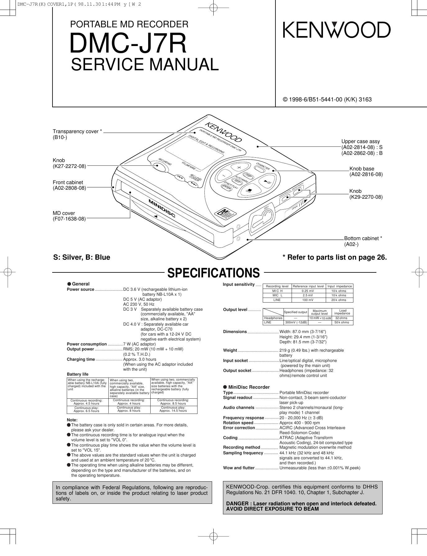
Kenwood DMCJ 7 R Service Manual

This is the 28 pages manual for Kenwood DMCJ 7 R Service Manual.
Read or download the pdf for free. If you want to contribute, please mail your pdfs to info@audioservicemanuals.com.

Page: 1 / 28
left right
Kenwood DMCJ 7 R Service Manual

Extracted text from Kenwood DMCJ 7 R Service Manual (Ocr-read)


Page 1

DMC-J7R 2 CONTENTS / ACCESSORIES / CAUTIONS SPECIFICATIONS .........................................Top cover CONTENTS / ACCESSORIES / CAUTIONS ...............2 CONTROLS .................................................................3 DISASSEMBLY FOR REPAIR .....................................4 BLOCK DIAGRAM .......................................................6 CIRCUIT DESCRIPTION .............................................7 TROUBLE SHOOTING ................................................8NOTE ON SCHEMATIC DIAGRAM ...........................14 PARTS DESCRIPTIONS ...........................................15 WAVEFORMS OF MD CIRCUIT ...............................16 PC BOARD ................................................................17 SCHEMATIC DIAGRAM ............................................21 EXPLODED VIEW .....................................................24 PARTS LIST...............................................................26 Contents Accessories Remote control (1) (A70-1210-08)Stereo headphone (1) (W01-0941-05) : K,P type (W01-0948-05) : T,E,E1,M typeRechargeable battery (1) (W03-5946-08): NB-L10AAC adapter (1) (W08-0669-08) : M type (W08-0672-08) : E,E1 type (W08-0673-08) : T type (W08-0674-08) : K,P type AC plug adapter (1) (E03-0115-05) : M typeConnecting cord (1) (E30-2836-08)Carrying case (1) (W01-0955-08) How to reset When this product is subjected to strong external interference (mechanical shock, excessive static electricity, abnormal sup- ply voltage due to lightning, etc.) or if it is operated incorrectly, it may malfunction. If such a problem occurs, do the following: 1. Unplug the AC adaptor from the AC socket. 2. Remove the battery. 3. Leave the unit completely unpowered for approximately 30 seconds. 4. Plug the AC adaptor back into the AC socket and retry the operation. If strange sounds, smell or smoke come out of the unit or an object is dropped into the unit, remove the AC adaptor from the AC socket immediately and contact an au- thorized KENWOOD service centre. Cautions DMC-J7R(K) COVER1,1P( 98.11.30 1:44 PM y[W 3

Page 2

Error messages Meaning Remedy BATT EMPTYThe battery run down. Charge the rechargeable battery or replace the alkaline batteries (or use the AC adaptor for power). BLANK DISCNothing is recorded. Replace the disc with a recorded disc. Can't COPYNo copy can be made because of the SCMS copyright system.Record using the analogue cable. Can't EDITA track cannot be edited. Change the stop position of the track and then try editing it. Can't RECRecording cannot be performed correctly due to vibration or shock in the unit.Re-record or replace it with another recordable disc. Can't WRITEEditing is impossible. Check the number of tracks. DEFECTThe disc is scratched. If the sound you hear is not right, try recording again. Replace the disc with another recordable disc. Din UNLOCKPoor connection of the digital cable. Connect the digital cable securely. DISC ERRORThe disc is damaged. Reload the disc or replace it. DISC FULLThe disc is out of recording space. Replace it with another recordable disc. HOLDThe unit is in the safety mode. Return the HOLD switch to its original position. LOCKED LOCK ERRORThe EJECT lever was moved during recording or editing.Turn off the power and remove the MiniDisc. NO DISCA disc has not been loaded. Load a disc. PB DISC PROTECTEDThe disc is write protected. You tried to record on a playback- only disc.Move the write protection knob back to its original position. Replace it with a recordable disc. POWER ?Improper power is being supplied. Use one of the specified power sources. SORRYSince a track number is currently being located or written to, the unit cannot accept your command.Wait for a while and try the operation again. SYSTEM ERRYou have come to the conclusion that the unit is out of order.To have it repaired, go to the distributor where you purchased the unit. TEMP OVERThe temperature is too high. Turn off the power, and wait for a while. TOC ERRORA large portion of the disc has been damaged.Replace it with another recorded disc. TOC FULLThere is no space left for recording character information (track names, disc names, etc.).Replace it with another recordable disc. Tr. ProtectThe track has been protected from being erased.Edit the track with the device on which it was recorded. U TOC ERRORA large portion of the disc has been damaged. There is an error in the recorded signal.Replace it with another recorded disc. Erase all of the signal errors, and then try recording again. ? DISCA disc which contains data other than music was played. There is an error in the signal from the disc.A disc which contains non-music data cannot be played. Replace it with another recorded disc. ERROR MESSAGES DMC-J7R 3 CONTROLS Main Unit 1. Monaural Long-Play Mode Indicator 2. Record Indicator 3. Level Meter 4. Repeat Indicator: 5. TOC Indicator 6. Battery Indicator: 7. Random Indicator 8. Track Number Indicator 9. Character/Time Information Indicator 10. Synchro Recording Indicator 11. Disc Mode Indicator 12. Disc Name Indicator 13. Track Name Indicator 14. Remaining Recording Time Indicator 15. Total Track Number Display 16. Record/Track Mark Button 17. Volume/Name Select Buttons: +, - 18. Display/Lowercase Characters Button 19. Character Button 20. Stop/Power Off/Charge Button: /OFF 21. Play/Pause Button: 22. Fast Reverse/Fast Forward/Record- ing LevelControl/Cursor Buttons: / 23. Enter/Fast Play/Synchro Button 24. Edit/Auto Mark/Time Mark Button 25. Eject Lever 26. Bass/Delete Button 27. Mode/Insert Button 28. Microphone Input Socket 29. Hold Switch 30. Rechargeable Lithium-Ion Battery Compartment 31. Optical/Line Input Socket 32. Headphones Socket 33. 5V DC Input Socket 34. Battert Case Connection Terminals 12345 6 7 8 9 10 11 12 13 14 15 16 17 18 19 20 21 2223 24 25 26 27 29 34 30 33 28 31 32 Remote Control Unit 1. Synchro Recording Indicator 2. Character/Time Information Indicator 3. Record Indicator 4. Repeat Indicator: 5. Random Indicator 6. Disc Mode Indicator 7. Total Track Number Display 8. Track Number Indicator 9. Battery Indicator: 10. Headpones Socket 11. Hold Switch 12. Play Mode Button 13. Volume Buttons: +, - 14. Bass Button 15. Display Button 16. Play/Pause Button: 17. Stop/Power Off Button: 18. Fast Reverse/Fast Forward Buttons: / RANDOM TOTAL 1 RECSYNC 12 13 14 11 15 16 17 18 101 62 3 4 5 789 NAMES OF CONTROLS AND INDICATORS ÖA rechargeable lithium-ion battery is the only kind that can be used. Even if the battery supplied with the unit is not used, you should charge it at least once every three months because of the special quality of this battery. ÖThe rechargeable battery can be charged approximately 300 times. ÖDo not use any battery other than that specified. Use of other batter- ies maycause malfunctions. ÖWhen the operating time is reduced to about half the normal amount of time, even after a full charge is per- formed, replace the battery with a new one. ÖWhen charging or when using the rechargeable battery, use it within an ambient temperature range of 5˚C to 35˚C. ÖIf the rechargeable battery is used in a cold environment, the operating time will decrease.Since the rechargeable battery is vulnerable to damage, please note the following. ÖDo not carry the battery in your pocket or a bag together with metal objects (keys, coins, jewelry, etc.). The battery may short out and gen- erate significant amounts of heat. ÖDo not short-circuit the terminals as they will become very hot and will damage the battery. ÖDo not dip the battery in water, do not dispose of it in a fire, and do not take it apart. To avoid damaging the battery and shortening its service life, please note the following. ÖDo not drop or subject the battery to shock. ÖDo not insert objects (metal etc.) into the battery compartment of this product or into the rechargeable bat- tery. Do not get the terminals dirty. If the rechargeable terminals are dirty, the operating time may be shortened or it may not be possible to charge the battery. ÖAfter the rechargeable battery is charged or used, it will get slightly warm. This is normal. 7 Notes about the rechargeable battery DMC-J7R(K) COVER1,1P( 98.11.30 1:44 PM y[W 6

Page 7

DMC-J7R 8 TROUBLE SHOOTING Yes Check whether there is defective solder joint of audio signal line between IC703 and J703 No Yes Is audio wavefrom output from J703 pins 3 and 4. Check the pins 5 and 6 of IC703. No Yes Is audio wavefrom output from IC703 pins 18 and 19. Check IC201 pins 70 to 72, pin 74 and IC501 pins 9, 10, 11, 15 No - Abnormal display No Yes Is waveform output from IC 401 pins 45 to 47? Check for pattern breakage of flexible PWB, check for defects of display microcomputer (replace the display unit).Is waveform output from CNS 482 pins 1 to 3? Are the pin7 (VCC) and pin 6 (GND) normal? - Playback state cannot be set Is initialization performed normally in case of high- reflection disc playback?Yes Check between IC401 and CNS482.No Check the periphery of IC401. Does the playback time display advance? Yes Position check in INNER mode Check IC201 and IC202 connection line. Is the lead-in photointerrupter set to OFF when the optical pickup moves to the innermost periphery in NORMAL mode? (Is TP660 in H level?). Check the lead-in photointerrupter, mechanical flex PWB soldering and CNS601 connection. No Ia an attempt to repeat repeatedly the TOC part performed on the low-reflection disc?Yes No No Replace the disc. No - Audio playback clrcult When it has been ascertained that the address up to cluster address is normal in the TEST mode. Yes Is audio wavefrom output from IC501 pins 19 and 20? Check headphones jack,and periphery of headphone. Although the playback time display is acting., no sound is given during playback in the normal mode. It is advisable to use the TEST mode (refer to Error Data Display Mode, P15) indicating the causes of troubles before starting repair. Causes of operation errors (up to 10 errors) are recorded as error codes. This information is useful for repair. When does not functionWhen the CD section does not operate When the objective lens of the optical pickup is dirty,this section may not operate.Clean the objective lens,and check the playback operation.When this section does not operate even after the above step is taken,check the following items. Remove the cabinet and follow the troubleshooting instructions. "Track skipping and/or no TOC(Table Of Contents) may be caused by build up of dust other foreign matter on the laser pickup lens. Before attempting any adjustment make certain that the lens is clean. If not, clean it as mentioned below." Turn the power off. Gently clean the lens with a lens cleaning tissue and a small amount of isopropyl alcohol. Do not touch the lens with the bare hand. Is the power supply turned on when the remote control button or main unit button is pressed?NoPerform the check stated in item "Power is not turned on when the PLAY button is pressed". Perform the check stated in item "Abnormal display". No Yes Does the display operate normally? Is playback state set?Yes Perform the check stated in item "Playback state connot be set". No Is audio output normal?Yes Perform the check stated in item "Audio playback circuit". No Is recording/playback operation normal?Yes Perform the check stated in item "Recording/playback operation". No - Power is not turned on when the / button is pressed. No NoYesCheck the periphery of remote controller and main unit headphone terminal (J703) and IC401. No Is the pin 57 of IC401 in H state? Is operation normal when the main body button is pressed? Check the position of Hold switch. Is power turned on when the remote control button is pressed? No Are IC401 pin 97 set to "L"?Check the DISC IN (SW901) switch of mechanism PWB. Yes Yes Is clock supplied to the pins 11 and 14 of IC401? NoCheck that voltage is applied to the periphery of IC403. Yes Is 2.5V applied to TP811? NoCheck whether there is solder touch of part connected to the +2.5V line. DMC-J7R(K) COVER1,1P( 98.11.30 1:44 PM y[W 15

Page 19

ABDFHJCEG I 2 1 3 5 7 4 6 1413 1211 10 9 8 7 6 5 4 3 2 1 16 15 14 13 12 11 10 9876543218 7 6 5 4 3 2 1 5 4 321 4 3 2 1 8 7 6 5 4321 14 13 12 11 10 9 87 6 5 4 3 2 1 20 19 18 17 16 15 14 13 12 11 10 9 8 7 6 5 4 3 2 1 25 24 23 22 21 20 19 18 17 16 15 14 13 12 1127 26 28 29 30 31 32 33 34 35 36 10 9 8 7 6 5 4 3 2 1 5 4 3 2 1 109 8 7 6 543211 2 3 4 1 2 3 45 6 7 8 5 4 321 24 23 22 21 20 19 18 17 16 15 14 1312 11 10 987654321 33 32 31 30 29 28 27 26 25 24 23 22 21 20 19 18 17 16 15 14 13 12 11 10 9 8 7 6 5 4 3 2 17 6 5 4 3 2 1 1 2 3 4 5 6 7 8 9 1011 12 1 2 3 4 5 6 7 8 9 10 1112 1314 1516 17181920 123456789 2627 28 2627 28 29 3031 32 3334 35 3637 38 39 40 41 42 43 44 45 46 47 48 49 50 51 52 53 54 55 56 57 58 59 60 61 62 63 64 65 66 67 68 69 70 71 72 73 74 75 76 77 78 76 77 78 79 80 81 82 83 84 85 86 87 88 89 90 91 92 93 94 95 96 97 98 99 10 11 12 13 14 15 16 17 18 19 20 21 22 23 24 25 100 50 49 48 98 99100 1 2 3 4 5 6 7 8 9 10 11 12 24 23 22 21 20 19 18 17 16 15 14 1325 2627 2829 30 31 323334 3536 48 47 46 45 44 43 42 41 40 39 38 37 1 2 3 4 5 6 7 8 90 11 12 1 1 2 3 4 5 1 2 3 4 56 7 8 9 10 11 12 13 14 15 16 17 18 19 20 21 22 23 24 25 22 23 24 25 26 27 28 29 30 31 32 33 34 35 36 37 38 39 41 40 42 43 44 45 46 47 48 49 50 51 52 53 5451 52 53 54 55 56 57 58 59 60 61 62 63 64 65 66 67 68 6970 71 72 73 74 7576 77 78 79 80 81 82 83 84 85 86 87 88 89 90 91 92 93 94 95 96 97 98 99 100 70 71 72 73 74 75 1 2 3 4 5 67 8 1 2 345 1 2 3 4 5 67 8 1 2 345 123456789 10 11 12 13 14 15 16 17 18 19 20 21 22 123456789 10 11 12 13 14 15 16 17 18 19 20 21 22 1 2 3 4 5 67 8 1 2 3 4 5 6 1 1 2 2 3 3 44 5 1 2 3 4 5 61 2 3 1 2 345 6 1 2 3 4 5 6 1 2 3 4 5 6 7 8 9 10 11 12 15 14 13 18 17 1621 22 23 24 20 19 1 2 3 4 5 6 7 8 9 10 11 12 15 14 13 1817 16 2120 23 2422 19 1 2 3 4 57 8 9 4M D-RAM AUDIO AMP. CONSTANT CURRENT DRIVE POWER DRIVE IC821 IR3M09N MAIN PWB-A1 33 1MIC INLINE JACK PWB-A2 1 71 14 FLEXIBLE PWB FLEXIBLE PWB KEY FLEXIBLE PWB UNIT LCD DRIVER GND P-MODE C-MODE ENTER DISPLY VOL DOWN VOL UP BASS EDIT REC SKIP DOWN SKIP UP STOP PLAY LCD 1 16 SW902 DISC PROTECTHEAD PH901 COMW U V-“ +-“ + M M M PWB FLEXIBLE PICKUP UNIT FLEXIBLE PWB RF1 RF3 RF4 RF2 F-“ T+ F+T-“F E AGND LDVAR DGNDDGNDVCC CVCCCOMLDON A B MP/R VCC OPIC CLOCK RKEY RPLAY VSSNCVDD OUT CIN MCCK EFMO SPDRR GND VCC GND CSL2 CSL1 CST COM WIN VIN UIN UOUTRF WOUT NCVCC FG BRK-“ BRK+ STBY RIB VOUT VM DISCIN DISCPR INNSW PDCNT SPDRF SLDRF SLDRR DCNT1 VG VC LG GND VD3 FO3 RO1PGND RO3 VD3 VD4 PGNDRO4 RO2 RI4FI4 FI3 RI3 VD4 FO4 RI2 FI2 FI1 RI1 VD2 FO2 PGND VD2 VD1 PGND FO1 VD1 OE PS CLK AGND NC NC T+ T-“F-“ F+ LDCNT1 LDCNT2 FODRF FODRR TRDRF TRDRR G I2 VCC I1 G VS O2 NC O1 NC NCPLVDRY PLVDCI RKEY HKEY1 HKEY2 LDVAR TEMP SYWR SYRD SYRS RKEY HSTOP SYD0 SYD1 SYD2 DSPSCK DSPDAT DSPSTB BEEP CLOCK SYD3 SYD4 SYD5 SYD6 SYD7 RPLAY LDON OPICGA RFLAT VCC GND RACLK RADAT PBLAT RCLAT PBOPON MCPGIN INPGIN INPGCK EMPH0LDON HFONSYD3 SYD4 SYD5 SYD6VLIM AVDD AVREF0PLVINN DINT SENSEFOK XRT XRT FOK DINT RESET SENSE XT1 XT2 X1 VSS X2 OEMVDD SLCNT3 SLCNT5 SLCNT1 SLCNT4 SLCNT6 SLCNT2 SWPUP PCNT2 CKSTP DISCININNSW DISCPRPDCNT VPP PHOLDPCNT1 CIN ELON PSLINN PSLDCI PSLDRY TEST1 TEST0 SPIN VDD EPCS INPGCK RCPCNT EEPK RTCCK EEPD RTCDT RTCWR RTCCE VSS EMPH0 HPLAY HREC LI RI AGNDLIHP LOUTRIHP ROUT DGND VEE VCC DIN OPTCNT INPGCK INPGIN MCPGIN R-CH R-CH L-CH L-CH RESET RCAULT PBAULT PBMUTE BEEP AUDATAAUSCLK MCPGIN INPGIN INPGCK OPTCNT DIN PBOPON BEEP PBLAT RCLAT RADAT RACLK ADPON DAPON DFCK LRCK BCLK ADDATA DADATA EMPH1 EMPH0 RMDAT DEM0 DEM1 RKEY RPLAY SCLK STDO MCLK LRCK STDI PWAD PWDA PBAULT BEEP AUDATA AUSCLK RCAULT PBMUTE RESET INPGIN MCPGIN DIN OPTCNT INPGCK VCCMIC VCC2.8X VCC2.8 DGND VD SDTI CMODE DEM1 DEM0 AOUTL AOUTR VCOM AGND VB VAVRDA VRADAINR VCMRVCMLAINL PWDA PWADMCLKLRCKSCLK SDTO ROUT LOUT VCC DGND RIHP LIHP AGNDRI LI VEE L-CHR-CH KEY PLAY DATA NC NC NCNC HKEY1 HKEY2 TEMP AVSS LDVAR MDOUT AVREF1 SYD0 SYD1 SYD2 SYD7 SYWR SYRD SYRS RKEY VCC CS SK DI DO GND PRTCT BEEP CNTRY PCNT1 EAOUT GNDOUTVCC PWMSTATEROSC OSC VREF EAIN-“ DB EAIN+OSCIN OSCOUT EJECTHDON DSPSTB DSPDAT DSPSCK RPLAY HSTOP KHOLD MCPGIN INPGIN F-“ T+ F+ T-“ EFMMON ROUT GOUT TTR EFMAGI EFMAGC AGND AVCC EFMI EFMO RF2-1 ADAGADAGCADIPIADIPO ADLPFO22KO 22KI WBO TCGO AOUT BOUT EOUT FOUT DVCC DATA CLOCK LATCHDTEMP DGND AGND SGAINDISC STBY AVCCBIASFIN EIN BIN AIN TCGI RFADD REFO REFI RF4 RF3 RF2 RF1 BIASADIP AGC EMF AGC DIFF DIFF SW and R HPF LPF LOGIC LDCNT1 RAA10 ACRCERPLCK SYRS FEMONDADATAADDATA DFCK BCLK LRCK DGND VDD3 DOUT DIN X1O X1I VPD VXI ADPON DAPON OPTCNT DCNT1 EMPH1 LDCNT2 X700KO TOTMON TEMON SBCK SBO SBSY SFSY FOK SENSE COUT MCCK DINTX RSTX SYSD0 SYSD1 SYSD2 SYSD3 SYSD4 SYSD5 SYSD6SYRDX SYWRX VBAT WBI TEST1 TEST0 FODRR FODRF TEST2 X176KO X176KO TRDRF TRDRR SLDRF SLDRR SPDRF SPDRR TCG AGND AIN FIN EIN BIN DGND VDD1 VDD1 DGND EFMI AVCC DGND VDD1 RAD0 RAD1 RAWEX RARASX RAA9 DGND VDD2 RAD3 RAD2 RACASX RAOEX RAA8 RAA7 RAA6 RAA5 RAA4 RAA0 RAA1 RAA2 RAA3TCRS EFMO I/O1 I/O2 WE RAS A9 A0 A1 A2 A3 VCCA4 A5 A6 A7 A8 OE CASI/O3 I/O4 GND GNDVCC OSCOUTOSCIN EAIN+ DB EAIN-“ VREF OSCROSC STATEPWMVCC OUT GND EAOUT RMDAT OPICGA RFLAT RACLK RADAT PBLAT RCLAT PBOPON VCC GND OUTVSSVDD PLVDRY PLVDCI PLVINN HPLAY HREC RCPCNT PCNT1 RCPCNTDSPDAT DSPSCK DSPSTB PHOLD PCNT1PCNT2 HPLAYHREC RPLAY PCNT2 PHOLD PSLDCI PSLINN PSLDRY PLVDCI PLVINN PLVDRY PDCNT DISCPR INNSW DISCIN ADDATA DFCK BCLK LRCK DIN ADPON DAPON EMPH1 OPICGALDVAR LDON TEMP RFLATRACLKOPTCNT RADATXRT PSLDRY PSLDCI PSLINN RKEY HKEY2 HKEY1 MICOM2.5V EFMO HSTOP HPLAY HREC HKEY2 HKEY1 FODRF FODRR TRDRF TRDRR SLDRF SLDRR SPDRF SPDRR LDCNT1 LDCNT2 DCNT1 FOK SENSE CIN MCCK DINT SYD0 SYD1 SYD2 SYD3 SYD4 SYD5 SYD6 SYD7 SYWR SYRD SYRSDADATA NC NC 97SYSD7 D493 015Z5.1Y CN101 L863 4.7 D861 RB491DC863 1/10 C864 33/6.3 L171 10 100K R442 R444 2.7K C911 0.1 L651 0.47µH C600 15/10 D494 15AZ7.5Y C774 1 CN451 CN482 C843 100P(CH) C868 1 C865 1/10 L862 47 C869 33/6.3 POWER DRIVE IC841 IR3M09N L841 4.7R844 15K C848 1/6.3 R846 10K C845 47P (CH) C844 100P(CH) R843 100KC842 22P(CH) R848 220K R847 330KR852 1.5M IC202 IX2567AF Q101 2SA17457 C104 0.027C107 0.012 C131 330P(CH) C202 10/6.3 C109 1/6.3 C106 0.22/16 R101 22K R102 22K C201 1 C110 0.22/16 CK112 IC201 LR37648B R222 1MR207 680 IC101 IR3R55 C111 0.0033 C102 1/6.3 R104 22K R103 22K C161 1/6.3 L202 10µH R154 1.2K L100 10µH L201 0.47µH C100 10/6.3 R841 100K C850 0.001CN701 R849 33K D822 RB521S30 R831 100K C829 0.01 C823 100P(CH) L821 4.7 R823 100K R828 270KR824 15K C825 68P (CH) R829 33K C828 1/6.3 R827 300K R826 10KR821 100K C830 0.001 R832 3.3M C822 39P (CH)C824 100P(CH) C847 10/10 L842 10 C846 1/10 C827 3.3/10 D821 F1J2F C826 1/10 L822 10 C821 220/4 C810 0.33/10 R811 180K R810 180K C172 33/6.3 C171 33/6.3 XL201 33.8688MHz C211 5P(CH) R203 100 C212 5P(CH) C622 2.2 IC601 MPC17A39 C443 0.47/10C441 10P(CH) C442 680P IC441 TC7W14FU INVERTER R443 39K R441 12K R408 100K IC404 7SH00FU R403 22K R404 150K IC401 IX2680AF TP144 C103 1/6.3 C902 0.01 10K R909 R908 100KR907 180K R903 150 R904 22KR901 1 R902 1 IC901 BA6965FV C907 0.0022 C905 0.0022C909 0.047 C906 0.0022 C908 0.47 C910 0.047 100K R905 R906 270K C903 3.3/10 C866 1/10D862 RB521S30 IC702 TK71345M R878 100K R874 470K C878 3.3/10 R873 1K IC872 TC7W32FU C877 10/6.3 IC871 S8327B30 C874 10/10 C872 1/6.3 Q871 NDS335N C871 1/6.3 D873 1SS372 C873 1 C849 0.01 R851 100K D842 RB521S30 D802 SB10015C IC803 NDH831N C431 0.0471SS361D431 330K R431R482 18KC481 0.1 R481 36K R421 100K R161 1.2K C165 0.033 R205 560K C205 0.1R206 220K C651 1 IC651 LB1638M R420 1K R419 1K C357 0.1 IC351 74ACT02F HEAD DRIVE C354 0.1 C351 100P(CH)D352 SB0209CP D351 SB0209CP0.039 C361 R361 8.2 C353 10/6.3 R423 22K R425 22K R424 22K C875 0.22/16 R877 100KR876 100K C880 0.01 C879 1/6.3 IC874 TC7S00FU CHARGE DRIVER R882 100K R881 100K R402 10K R105 390K Q351 2SK2909Q353 2SK2909 Q352 2SK2911Q354 2SK2911C123 390P C124 390P C121 270P(CH) C122 270P (CH)R204 1K C203 0.1 C207 0.1 R879 100KR880 100K R809 100K R422 33K R412 10KR411 100K IC402 S29L294A R415 1K R413 1K R414 1KC401 0.1 SW401 EJECTR406 100K SW402 HOLD R405 10K R407 10K R409 100K D877 1SS360C886 10/10L886 0.47µH IC804 RN4904 Q842 NDS335N Q822 NDS335N C881 1/6.3 D875 1SS378 S80821LNIC431 IC875 TK71325M R872 100K Q872 DTC144 EE Q873 2SJ305 IC873 S80827LN Q401 2SA17457 R400 3.9K L601 47µH C601 1/6.3L602 47µH C602 1/6.3 L603 47µH L604 47µH C603 1/6.3C604 1/6.3 L600 2.2µH L608 47µH R601 56K TP601R458 56K R457 18K R456 8.2K R455 5.6K R454 56K R453 18K R452 8.2K R451 5.6K L610 47µH L609 47µH C610 1/6.3C609 1/6.3R922 100K R921 330 L204 R861 100K R106 56K C608 3.3/10R426 100K D831 1SS372 C831 0.1 C832 0.1 D201 1SS369 D841 F1J2F D871 RB491D 47 TP901 R875 100K IC876 RN4904R814 3.9K R818 10K R815 3.9K C802 1 Q801 2SD1950 D801 015Z5.1Y R816 1.2K IC800 HN1C03FU R801 680K R819 270 C808 1/6.3 R808 39K R807 27K R806 680K C807 0.1R805 470K C806 3.3/10L801 1 C805 100/6.3 C804 1/6.3 IC801 HAT1025R CONSTANT CURRENT DRIVE R804 100K Q803 DTC144 EE Q802 DTC144 EE R803 100K R802 390KC803 0.1 IC805 UMD3ND800 RB491D L888 CORE L887 CORE C112 0.033 R817 680 C759 0.056 C761 1/6.3C762 1/6.3 C702 10/6.3 R756 27K R701 100 C756 0.68 R762 3.3K R761 3.3K R754 330K R757 27K C757 0.68 IC703 IR3R54N AUDIO AMP. IC701 IR3R54N C703 0.01 R703 150K C758 3.3/10 C755 0.01 C753 1 C701 10/6.3 R702 100 L771 47µH C771 33/6.3 C772 33/6.3 C773 0.22/16 IC771 TK71225M C775 0.01 L710 0.47µH C710 0.1 C510 2.2 C509 2.2 R502 470 R501 470 C502 0.0022C501 0.0022 C504 3.3/10C503 3.3/10 L500 4.7µH L772 4.7µH C508 1/6.3 C500 10/6.3 IC501 AK4514VF R500 4.7 C507 10/6.3 D492 015Z5.1Y L491 4.7µH C722 3.3/10C721 3.3/10 C723 0.001 C735 0.001C736 0.01 C451 0.001C724 0.001 C731 0.22R727 10KR723 6.8K R724 6.8K C725 3.3/10 C727 1Q721 2SC4213B R725 100 R726 39K R728 1K C726 3.3/10 R713 10K Q711 RN1444A R717 1K C712 100P (CH) C714 1/6.3 (CH)R714 10K C713 1/6.3 C711 100P (CH) C715 0.1 R715 100K R716 100K C734 0.1 C733 0.1 R720 8.2K R719 8.2KR712 5.6K R711 5.6K C754 1 R753 150K L751 47µH L752 47µH C768 0.22/16R752 82 C767 0.22/16R751 82R729 2.7K R730 2.7K TP721 C491 0.1 D491 015Z5.1YR504 20K R503 20K R767 1K R768 1K R766 10 R765 15 C751 0.082 C752 0.082R492 1K C952 47/4 C951 47/4 L452 L454 L453 L457 L458 L456 C130 0.1 J702 J703 HEADPHONE J701 J801 DC IN L702 L703 L713L714 L704 L712 L711 X700K M902 SLED MOTOR M901 SPINDLE MOTOR M903 LIFT MOTOR SW901 DISC IN X176KO CK102 CK103 CK104CK101 TP145 TP132 CK108 TP133 TP130 TP131 CK107 TP100 CK111 CK110 CK109TP139 TP119TP115 TP105TP101 TP109 TP106TP102 TP108 TP103 TP114TP110 TP118TP111 TP121 TP122TP120 TP117TP116 CN601TP651 TP652 TP653 TP654 TP655 TP656 TP657 TP658 TP659 TP660 TP661 TP662 TP663 TP664 TP665 TP666 TP610 NAND GATE MOTOR DRIVE TP401 TP403 TP402 TP413TP208 CK204 CK205 CK206 CK203 CK202 CK201TP211 TP210 TP209 TP202 TP201 CK207 TP206 TP203 TP204 TP205 TP200 TP405TP404TP406TP412 TP407 TP411 TP408 TP409 TP410 TP810 TP762 TP763 TP764 TP765 TP766 TP767 TP768 TP769 TP770 TP771 TP772 TP773 TP774 TP775 TP776 TP777 TP778 TP779 TP780 TP783 TP784 TP785 TP787 TP781 TP761TP561 TP562 TP563 TP564 TP565 TP566 TP567 TP568 TP569 TP570 TP571 TP572 TP573 TP574 TP575 TP576 TP577 TP578 TP579 TP580TP581 TP582TP584 TP585TP586 TP588 TP789 TP790 TP791 TP792TP793 TP590 TP591 TP592TP593TP453 TP452TP451 TP461 TP454 TP464 TP455 TP456 TP457 TP458 TP459 TP460 TP462 TP463 TP481 TP482 TP483TP487 TP486 TP485 TP484 TP729 TP712TP713 TP711TP714 TP703 TP705TP708 TP701 TP709 TP704TP702TP707 TP722 TP723TP724 TP725TP726 TP 727TP728 TP807 TP808 TP809BATTERY TERMINAL EXT.BATTERY TERMINAL TP805 TP806 TP804 TP803 TP811 TP207 TP500 TP802TP801 DTC144EE 2SJ305 TC7S00FU LB1638M CAUTION:For continued safety, replace safety critical components only with manufacturer's recommended parts (refer to parts list). indicates safety critical components. For continued protection against risk of fire, replace only with same type and rating fuse(s). To reduce the risk of electric shock, leakage-current or resistance measurements shall be carried out (exposed parts are acceptably insulated from the supply circuit) before the appliance is returned to the customer. NOTES ON SCHEMATIC DIAGRAM can be found on page 14. The numbers 1to *are waveform numbers shown in page 16. hL g 1 98.11.30 1:53 PM y[W 2

Page 25

DMC-J7R 28 PARTS LIST J703]E11-0383-08 JACK,HEADPHONE J801]E03-0360-08 JACK,DC IN L100]L90-0307-08 COIL L171 L90-0075-08 CHOKE COIL L201]L90-0308-08 COIL L202]L90-0307-08 COIL L204]L90-0316-08 IMPEDER L451 RK73GB1J000J CHIP R 0 J 1/16W L452~454]L90-0318-08 IMPEDER L456~458]L90-0317-08 IMPEDER L491]L90-0309-08 COIL L500 L90-0071-08 COIL L501 RK73GB1J000J CHIP R 0 J 1/16W L600 L90-0083-08 CHOKE COIL L601~604 L90-0065-08 COIL L608]L90-0310-08 CHOKE COIL L609, 610 L90-0065-08 COIL L651]L90-0308-08 COIL L702, 703]L90-0317-08 IMPEDER L704]L90-0318-08 IMPEDER L710]L90-0308-08 COIL L711]L90-0318-08 IMPEDER L712~714]L90-0317-08 IMPEDER L751, 752 L90-0094-08 CHOKE COIL L771 L90-0065-08 COIL L772 L90-0071-08 COIL L801 L90-0073-08 CHOKE COIL L821 L90-0074-08 CHOKE COIL L822 L90-0075-08 CHOKE COIL L841 L90-0074-08 CHOKE COIL L842 L90-0075-08 CHOKE COIL L862 L90-0065-08 COIL L863 L90-0074-08 CHOKE COIL L871 L90-0065-08 COIL L886]L90-0308-08 COIL L887, 888 L92-0077-08 BEADS CORE XL201]L77-2228-08 CRYSTAL OSCILLATOR(33.868MHZ) R101~104 RK73GB1J223J CHIP R 22K J 1/16W R105 RK73GB1J394J CHIP R 390K J 1/16W R106 RK73GB1J563J CHIP R 56K J 1/16W R154 RK73GB1J122J CHIP R 1.2K J 1/16W R161 RK73GB1J122J CHIP R 1.2K J 1/16W R203 RK73GB1J101J CHIP R 100 J 1/16W R204 RK73GB1J102J CHIP R 1.0K J 1/16W R205 RK73GB1J564J CHIP R 560K J 1/16W R206 RK73GB1J224J CHIP R 220K J 1/16W R207 RK73GB1J681J CHIP R 680 J 1/16W R208, 209 RK73GB1J000J CHIP R 0 J 1/16W R222 RK73GB1J105J CHIP R 1.0M J 1/16W R223 RK73GB1J000J CHIP R 0 J 1/16W R351 RK73GB1J000J CHIP R 0 J 1/16W R361 RK73EB2B8R2J CHIP R 8.2 J 1/8W R400 RK73GB1J392J CHIP R 3.9K J 1/16W R402 RK73GB1J103J CHIP R 10K J 1/16W L :ScandinaviaK : USAP : CanadaR :MexicoC :ChinaI :MalaysiaE1,M :Silver Y : PX(Far East, Hawaii)T : EuropeE : EuropeG : GermanyV :China(Shanghai)K,P,E,T :Blue Y : AAFES(Europe)X :AustraliaQ :RussiaH :KoreaM :Other Areas indicates safety critical components. L :ScandinaviaK : USAP : CanadaR :MexicoC :ChinaI :MalaysiaE1,M :Silver Y : PX(Far East, Hawaii)T : EuropeE : EuropeG : GermanyV :China(Shanghai)K,P,E,T :Blue Y : AAFES(Europe)X :AustraliaQ :RussiaH :KoreaM :Other Areas indicates safety critical components. R403 RK73GB1J223J CHIP R 22K J 1/16W R405 RK73GB1J103J CHIP R 10K J 1/16W R406 RK73GB1J104J CHIP R 100K J 1/16W R407 RK73GB1J103J CHIP R 10K J 1/16W R408, 409 RK73GB1J104J CHIP R 100K J 1/16W R411 RK73GB1J104J CHIP R 100K J 1/16W R412 RK73GB1J103J CHIP R 10K J 1/16W R413~415 RK73GB1J102J CHIP R 1.0K J 1/16W R418 RK73GB1J000J CHIP R 0 J 1/16W R419, 420 RK73GB1J102J CHIP R 1.0K J 1/16W R421 RK73GB1J104J CHIP R 100K J 1/16W R422 RK73GB1J333J CHIP R 33K J 1/16W R423 RK73GB1J223J CHIP R 22K J 1/16W R424, 425 RK73GB1J223J CHIP R 22K J 1/16W R426 RK73GB1J104J CHIP R 100K J 1/16W R431 RK73GB1J334J CHIP R 330K J 1/16W R441 RK73GB1J123J CHIP R 12K J 1/16W R442 RK73GB1J104J CHIP R 100K J 1/16W R443 RK73GB1J393J CHIP R 39K J 1/16W R444 RK73GB1J272J CHIP R 2.7K J 1/16W R451 RK73GB1J562J CHIP R 5.6K J 1/16W R452 RK73GB1J822J CHIP R 8.2K J 1/16W R453 RK73GB1J183J CHIP R 18K J 1/16W R454 RK73GB1J563J CHIP R 56K J 1/16W R455 RK73GB1J562J CHIP R 5.6K J 1/16W R456 RK73GB1J822J CHIP R 8.2K J 1/16W R457 RK73GB1J183J CHIP R 18K J 1/16W R458 RK73GB1J563J CHIP R 56K J 1/16W R481 RK73GB1J363J CHIP R 36K J 1/16W R482 RK73GB1J183J CHIP R 18K J 1/16W R491 RK73GB1J000J CHIP R 0 J 1/16W R492 RK73GB1J102J CHIP R 1.0K J 1/16W R500 RK73GB1J4R7J CHIP R 4.7 J 1/16W R501, 502 RK73GB1J471J CHIP R 470 J 1/16W R503, 504 RK73GB1J203J CHIP R 20K J 1/16W R601 RK73GB1J563J CHIP R 56K J 1/16W R701, 702 RK73GB1J101J CHIP R 100 J 1/16W R703 RK73GB1J154J CHIP R 150K J 1/16W R711, 712 RK73GB1J562J CHIP R 5.6K J 1/16W R713, 714 RK73GB1J103J CHIP R 10K J 1/16W R715, 716 RK73GB1J104J CHIP R 100K J 1/16W R717 RK73GB1J102J CHIP R 1.0K J 1/16W R719, 720 RK73GB1J822J CHIP R 8.2K J 1/16W R723, 724 RK73GB1J682J CHIP R 6.8K J 1/16W R725 RK73GB1J101J CHIP R 100 J 1/16W R726 RK73GB1J393J CHIP R 39K J 1/16W R727 RK73GB1J103J CHIP R 10K J 1/16W R728 RK73GB1J102J CHIP R 1.0K J 1/16W R729, 730 RK73GB1J272J CHIP R 2.7K J 1/16W R751, 752 RK73GB1J820J CHIP R 82 J 1/16W R753 RK73GB1J154J CHIP R 150K J 1/16W R754 RK73GB1J334J CHIP R 330K J 1/16W R756, 757 RK73GB1J273J CHIP R 27K J 1/16W R761, 762 RK73GB1J332J CHIP R 3.3K J 1/16W R765, 766 RK73GB1J300J CHIP R 30 J 1/16W ] New Parts Parts without Parts No.are not supplied. Les articles non mentionnes dans le Parts No.ne sont pas fournis. Teile ohne Parts No.werden nicht geliefert. 6 Ref. NoAdd- ress New Parts Parts No. DescriptionDesti- nationRe- marks ] New Parts Parts without Parts No.are not supplied. Les articles non mentionnes dans le Parts No.ne sont pas fournis. Teile ohne Parts No.werden nicht geliefert. 5 Ref. NoAdd- ress New Parts Parts No. DescriptionDesti- nationRe- marks DMC-J7R(K) COVER1,1P( 98.11.30 1:44 PM y[W 5