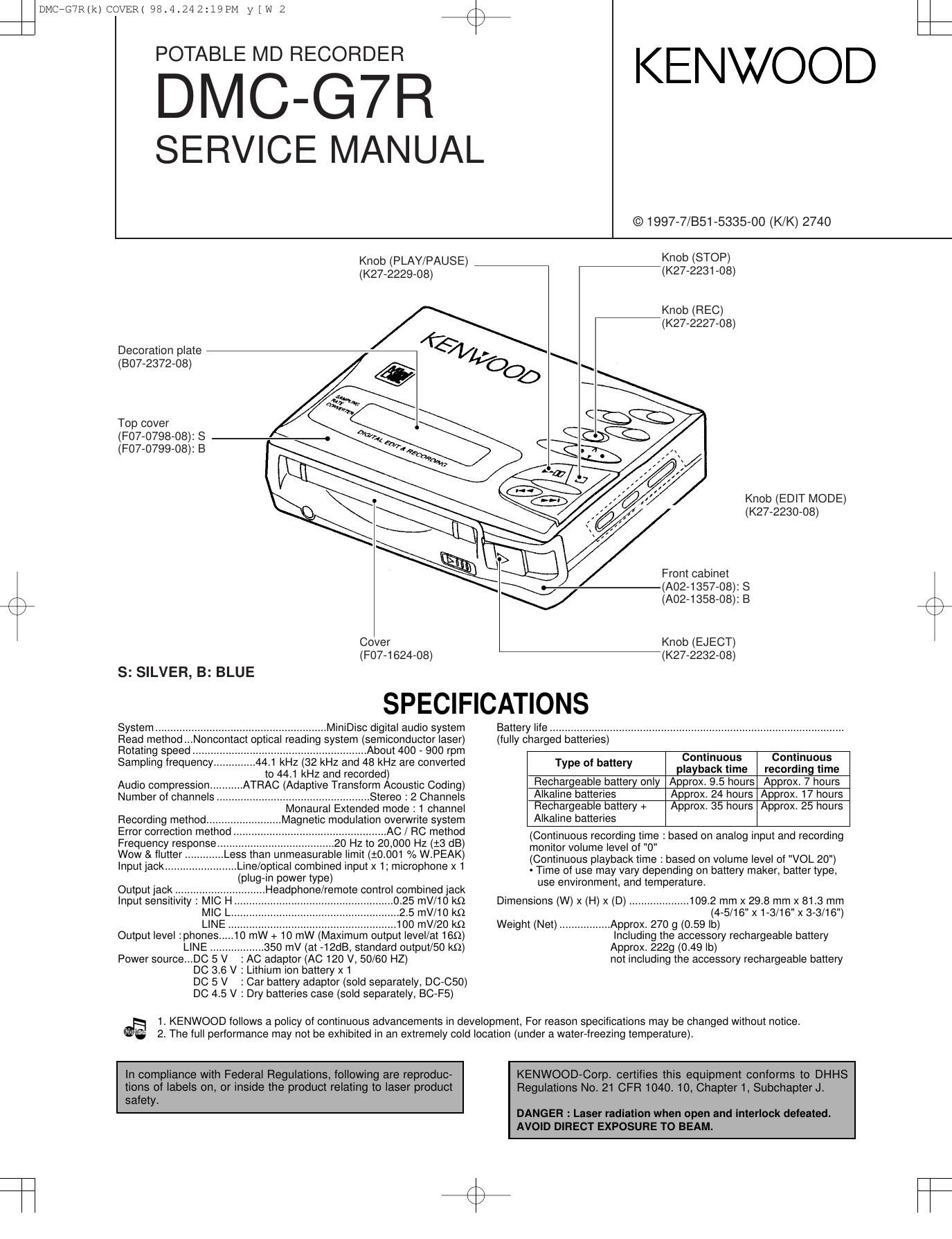
Kenwood DMCG 7 R Service Manual

This is the 30 pages manual for Kenwood DMCG 7 R Service Manual.
Read or download the pdf for free. If you want to contribute, please mail your pdfs to info@audioservicemanuals.com.

Page: 1 / 30
left right
Kenwood DMCG 7 R Service Manual

Extracted text from Kenwood DMCG 7 R Service Manual (Ocr-read)


Page 1

DMC-G7R 2 CONTENTS / ACCESSORIES Accessories AC adaptor(1) (W08-0668-08) : K (W08-0669-08) : M (W08-0670-08) : E (W08-0671-08) : T Rechargeable battery (NB-L5) (1) (W03-5679-08)Remote control (1) (A70-1129-05) : M Remote control unit (1) (A70-1177-05) : KETCarrying case (1) (W01-0918-08)Stereo headphone(1) (W01-0920-15) : MET Stereo headphone(1) (W01-0941-15) : KPatch cord (1) (E30-2836-08) Contents SPECIFICATIONS.......................................Front cover CONTENTS / ACCESSORIES....................................2 DISASSEMBLY FOR REPAIR.....................................3 TROUBLE SHOOTING................................................5PC BOARD................................................................19 SCHEMATIC DIAGRAM............................................23 EXPLODED VIEW.....................................................27 PARTS LIST...............................................................29 DMC-G7R(k) COVER( 98.4.24 2:19 PM y[W 3

Page 2

Caution on Disassembly Follow the below-mentioned notes when disassembling the unit and reassembling it, to keep it safe and ensure excellent performance: 1. Take the battery and minidisc out of the unit. 2. When disassembling the machine, be sure to withdraw the power plug from the socket in advance. 3. When disassemble the parts, remove the nylon band or wire holder as necessary. To assemble after repair, be sure to arrange the wires as they were. If a screw of different length is fitted to the MD mecha- nism (the screw of the part to be fitted to the MD mechanism chassis), it may contact the optical pickup, resulting in malfunction. 4. When repairing, pay due attention to electrostatic charges of IC. 1 Bottom Cover 1. Screw ..................... (A1) x5 7-1 2 Disc Cover 1. Screw ..................... (B1) x4 7-1 (Note) 2. Flexible PWB......... (B2) x1 3 Main PWB 1. Screw ..................... (C1) x3 7-2 2. Flexible PWB ......... (C2) x4 3. Soldering ............... (C3) x2 4 Front Cabinet 1. Screw ..................... (D1) x1 7-2 2. Remove the front cabinet in the arrow direction. REMOVALPROCEDURE STEPFIGURE Bottom Cover (B1) x2 Ø2x2mm (B1) x2 Ø2x2mm (A1) x2 Ø2x2mm (A1) x2 Ø2x2mm (A1) x1 Ø2x2mm (B2) x1 Disc Cover Figu re 7-1 Figure 7-2 Eject knob lever Eject leverLid opening and closing spring Lid opening and closing spring Lid opening and closing lever Engage the spring at the upper side.Lid opening and closing lever Figure Figure 7-3 Figure 7-4 Note: When removing the upper lid, at first turn the operation knob side in the arrow direction to remove. Installing the front cabinet (See Fig. 7-3.) 1. Make sure that the lid opening and closing spring has been engaged at the upper side as shown in Figure < A > . 2. Fit the MD lid right pin into the lid opening and closing lever to install it. Note: ¥ Take care since the antivibration rubber may come off. ¥ If the main PWB has been installed previously, fit the knob to the HOLD switch shown in Figure < B > . ¥ If the mechanism has been installed, the antivibration rubber may come off from the center cabinet fitting part when the front part of center cabinet is widened. (C1) x3 Ø2x2.5mm (D1) x1 Ø2x2.5mm (C3) x1(C2) x2 (C3) x1Main PWB Front Cabinet (C2) x2 Front Cabinet Lid opening and closing lever Center Cabinet Antivibration rubber HOLD knob MD lidMD lid right pin SW DMC-G7R 3 DISASSEMBLY FOR REPAIR DMC-G7R(k) COVER( 98.4.24 2:19 PM y[W 6

Page 9

TROUBLE SHOOTING DMC-G7R 10 5. TEST-REC Mode Step No. Setting MethodDisplayStep 1Test mode STOP state[ T E S T ]Step 2BASS buttonStep 3AUTO menu[ A U T O ]Step 4SKIP UP button x 4times (Or SKIP DOWN button x 6 times)Step 5TEST-REC menu[ T R E C ]Step 6When the DISP button is pressed, the process proceeds to (7). When the PLAY button is pressed, the process proceeds to (9). Step 7TEST-REC mode[ A d 0 0 5 0 ]Step 8PLAY buttonStep 9Continuous playback mode (groove)[ A P ]Step 10STOP buttonStep 11Test mode STOP state[ T E S T ] ¥ When the STOP button is pressed while the TEST-REC menu appears, or in the TEST-REC mode or continuous record mode, the mode changes to the TEST mode stop state. ¥ When the PLAY button is pressed while the TEST-REC menu appears, the continuous record is initiated from the current pickup position. ¥ Whenever the DISP button is pressed in the TEST-REC mode, the address changes as follows. 0050 Ñ 03C0 Ñ 0700 Ñ 08A0 Ñ 0050 Ñ ¥ Whenever the BASS button is pressed in the TEST-REC mode, the digit which is changed by the SKIP UP/DOWN button changes as follows. 0050 Ñ 0050 Ñ 0050 Ñ 0050 Ñ 0050 Ñ ¥ When the SKIP UP button s pressed in the TEST-REC mode, the digit of address specified by the BASS button is set to +1h.(0 to F) ¥ When the SKIP DOWN button is pressed in the TEST-REC mode, the digit of address specified by the BASS button is set to -1h. (0 to F) * When the SKIP UP/DOWN button is held down, the setting changes continuously, one cycle being 100 ms. ¥ When the VOL UP/DOWN button is pressed in the TEST-REC mode or continuous record mode, the laser record power changes. (Servo gain changes also according to record power.) * After the laser record power is indicated for one second, the address indication is restored. [ R P W ] ¥ : Address ¥ : Laser power cord ¥ Operation is disabled if the premastered disc or disc is in miserase-protected state. 6. INNER ModeStep No.Step 1Test mode STOP state[ T E S T ]Step 2BASS buttonStep 3AUTO menu[ A U T O ]Step 4SKIP UP button x 5 times (Or SKIP DOWN button x 5 times) Step 5INNER menu[ I N N E R ] Setting Method Display Step No. Step 6PLAY buttonStep 7INNER switch position measurement[ S Q ]Step 8STOP buttonStep 9Test mode STOP state[ T E S T ] Setting Method Display ¥ When the STOP button is pressed while the INNER menu appears, the mode changes to TEST mode stop state. ¥ : Address ¥When the STOP button is pressed while the TEST-PLAY menu appears, or in TEST-PLAY or continuous playback mode, the mode changes to the TEST mode stop state. ¥ When the PLAY button is pressed while the TEST-PLAY menu appears,continuous playback is initiated from the current pickup position. ¥ Whenever the DISP button is pressed in the TEST-PLAY mode, the address changes as follows. 0050 Ñ 03C0 Ñ 0700 Ñ 08A0 Ñ 0050 Ñ ¥ Whenever the BASS key is pressed in the TEST-PLAY mode, the digit which is changed by the SKIP UP/DOWN button changes as follows. 0050 Ñ 0050 Ñ 0050 Ñ 0050 Ñ 0050 Ñ ¥ When the SKIP UP button is pressed in the TEST-PLAY mode, the digit of address specified by the BASS button is set to +1h. (0 to F) ¥ When the SKIP DOWN button is pressed in the TEST-PLAY mode, the digit of address specified by the BASS button is set to -1h. (0 to F) * When the SKIP UP/DOWN button is held down, the setting changes continuously, one cycle being 100 ms. ¥ When the BASS button is pressed in the continuous playback mode, the number of jump lines changes as follows. 1 Ñ 10 Ñ 400 Ñ 1 * After the number of jump lines is indicated for one second, the address indication is restored.[ T R _ ] ¥ When the SKIP UP button is pressed in the continuous playback mode, the specified number of lines is jumped in the FWD direction. ¥ When the SKIP DOWN button is pressed in the continuous playback mode, the specified number of lines is jumped in the REV direction. * When the SKIP UP/DOWN button is held down, jump is repeated every approx. 100 ms. ¥Whenever the DISP button is pressed in the continuous playback mode, the indication changes as follows. * Pit section Continuous playback (SUBQ address indication)[ S Q ] | Continuous playback (C1 error indication)[ C E ] | Continuous playback (SUBQ address indication)[ S Q ] * Groove section Continuous playback (ADIP address indication)[ A P ] | Continuous playback (C1 error indication)[ C E ] | Continuous playback (ADIP error indication)[ A E ] | Continuous playback (ADIP address indication)[ A P ] ¥ : Address ¥ : C1 Error rate ¥ : ADIP Error rate ¥ : JUMP lines Mechanism Adjustment 1. Optical pickup grating inspecting method Figure 12-1 OPTICAL PICKUP GRATING DEVIATION MEASURING METHOD After the automatic adjustment is performed in the AUTO mode (test mode) with the aid of high refection MD disc ("COMPLATE" is displayed), the Lissajous's waveform (x-y) is adjusted. 1. Slightly loosen the 3 screws of spin motor, and make an adjustment, observing the Lissajous's wavefor. 2. After adjustment tighten the screws in arder of<1> , <2> ,< 3> . 3. It confirms Lissajous's wavwform ripple mark once again. Figure 12-2 1 3 2 Shifting the spin motor installation position, check the Lissajous's waveform. OSCILLOSCOPE GNDCH1CH2 XY TP141 GND TP132 EOUT TP133 FOUT100Kohm 470p 470p a b LISSAJOUS'S WAVEFORM LESS THAN A:B = 3:1 100Kohm DMC-G7R(k) COVER( 98.4.24 2:20 PM y[W 20