Kenwood DDX 8054 BT Service Manual

This is the 86 pages manual for Kenwood DDX 8054 BT Service Manual.
Read or download the pdf for free. If you want to contribute, please mail your pdfs to info@audioservicemanuals.com.

Page: 1 / 86
left right
Kenwood DDX 8054 BT Service Manual

Extracted text from Kenwood DDX 8054 BT Service Manual (Ocr-read)


Page 1

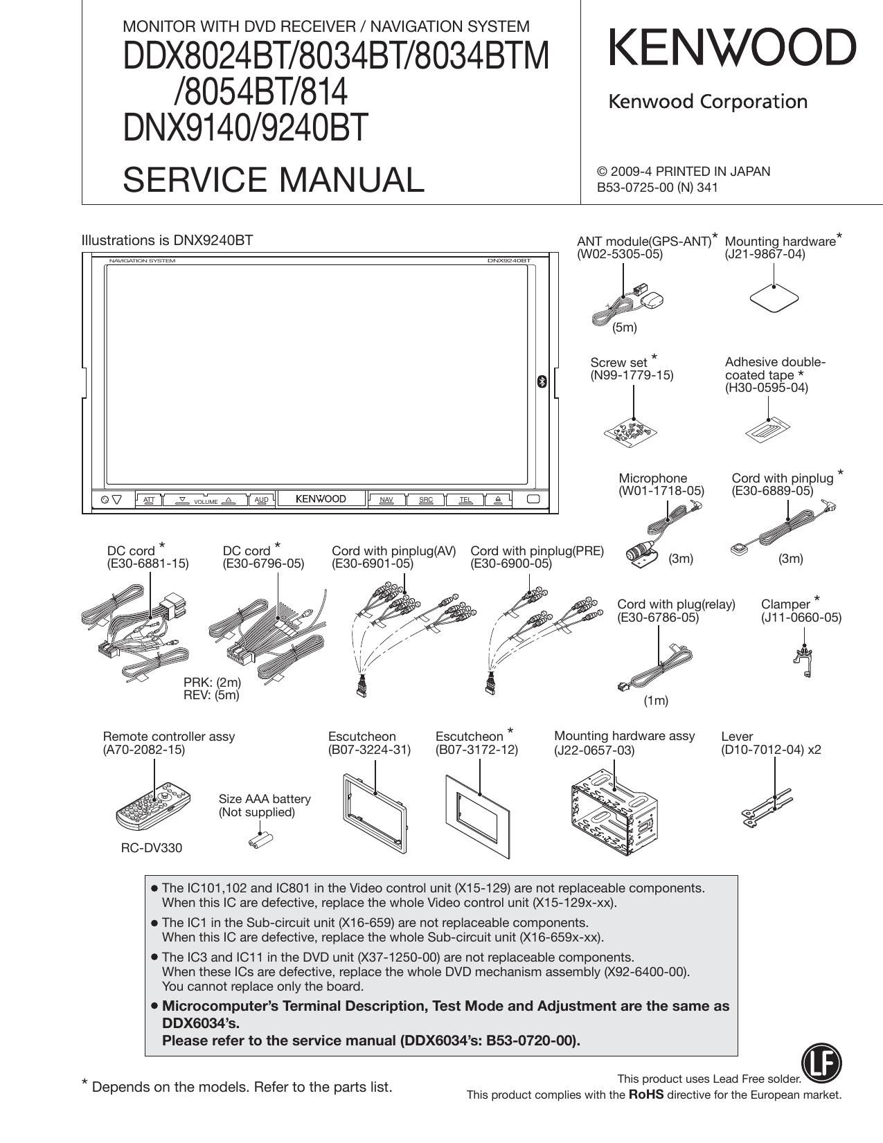
MONITOR WITH DVD RECEIVER / NAVIGATION SYSTEM

DDX8024BT/8034BT/8034BTM KENWOOD
/8054BT/814 Kenwood Corporation
DNX9140/924OBT

SERVICE MANUAL gigsgzzrrzarm

Illustrations is DNX924OBT ANT module(GPS-ANT)* Mounting hardware*
WWMMM mam... (W02-5305-05) (J21-9867-04)
(5m)
Screw set * Adhesive double-
0 (N99-1779-15) coated tape *
(H30-0595-04)
a v @
Microphone Cord with pinplug *
(av y?! El; WT é. fig) KENWOOD g g g. g C] (W01-1718-05) (E30-6889-05)
DC cord * DC cord * Cord with pinplug(AV) Cord with pinplug(PRE)
(E30-6881-15) (E30-6796-05) (E30-6901-05) (E30-6900-05)
fig Cord with plug(relay) Clamper *
// (E30-6786-05) (J11-0660-05)
/ 3/ 1
s /,r//
(1/ 2%
REV: (5m) g (1m)
Remote controller assy Escutcheon Escutcheon * Mounting hardware assy Lever
(A70-2082»1 5) (B07-3224-31) (B07-3172-12) (J22-0657-03) (D10-7012»04) x2

é

E / Size AAA battery l
. (Not supplied)
RC-DVSSO é

o The |C101,102 and |0801 in the Video control unit (X15-129) are not replaceable components.
When this IC are defective, replace the whole Video control unit (X15-129x-XX).

o The |C1 in the Sub-circuit unit (X16-659) are not replaceable components.
When this IC are defective, replace the whole Sub-circuit unit (X16-659x-XX).

O The ICS and |C11 in the DVD unit (X37-1250-00) are not replaceable components.
When these |Cs are defective, replace the whole DVD mechanism assembly (X92-6400-00).
You cannot replace only the board.

0 Microcomputers Terminal Description, Test Mode and Adjustment are the same as

DDX6034s.
This product uses Lead Free solder.

Please refer to the service manual (DDX6034s: 353-0720-00).
This product complies with the ROHS directive for the European market.

* Depends on the models. Refer to the parts list.

Page 57

:1: New parts
Parts without Parts No. are not supplied.
Les articles non mentionnes dans le Parts No. ne sont pas foumis.
Teile ohne Parts No. werden nicht geliefert.

DDX8024BT/8034BT/8034BTM/8054BT/814

DNX9140/924OBT

PARTS LIST

A N . . Desti- A N . . Desti-
Ref. No. 3 vev Parts No. Description nation Ref. No. 3 5 Parts No. Description nation
DDX8024BT/8034BT/8034BTM/8054BT/814 229 29 014.101 1 .14 ROLLER
DNX91 40/924031' 230 1H D19-0653-23 CLUTCH ASSY
208 1D >l< A22-3229-01 SUB PANEL ASSY E1
208 1D >l< A22»3230-11 SUB PANEL ASSY E201M1 232 1F E30-67B6-05 CORD WITH PLUG
208 1D >l< A22-3230-11 SUB PANEL ASSY M2X1 234 1F >l< E30-6889-05 CORD WITH PINPLUG (SWITCH.3M) KE1
208 1D >l< A22-3241-11 SUB PANEL ASSY K1 236 1E >l< E30»6901-05 CORD WITH PINPLUG (2AVIN)
208 1D >l< A22-3254-01 SUB PANEL ASSY K 237 1F >l< E30-6900-05 CORD WITH PINPLUG (3PRE+CENTAR)
238 2D E30-6888-05 CORD WITH CONNECTOR
208 1D >l< A22-3255-01 SUB PANEL ASSY R1
209 1D A52-O895-02 TOP PLATE 239 1D E39-0915-05+ WIRING HARNESS
PME1 3C A10-5300-51 CHASSIS ASSY 240 1C E39-1079-05 WIRING HARNESS
RC1 1E A70-2082-15 REMOTE CONTROLLER AS (RC-DV330) DC1 1E E30-6881v15 DC CORD KK1 R1
DC1 1E E30-68B1-15 DC CORD M1M2X1
- >l< B54-4722-00 INSTALLATION MANU (ENG.FREISPA) KK1 R1 DC2 1E E30-6796-05 DC CORD E1E201
- >l< B54-4723-00 INSTALLATION MANUAL (POR) R1
- >l< B54-4724-00 INSTALLATION MAN (E.F.G.D.I.S.P E1 E2 FC1 2C E39-1074v05 FLAT CABLE
- >l< B54-4725-00 INSTALLATION MANUA (ENG.RUS.UKR O1 F03 3C E39-1024-05 FLAT CABLE
- >l< B54-4726-00 INSTALLATION MANUAL (ENG) M1M2X1 FC4 2C E39-1073»05 FLAT CABLE
FC6 1D >l< E39-1102-05 FLAT CABLE
- >l< B54-4727-OO INSTALLATION MANUAL (S-CHI.HOR. M1 WH5 3D E39-1073-05 WIRING HARNESS E201M1
» >l< B54-472B-00 INSTALLATION MANUAL (ARA) M2
- B64-4338-00 INSTRUCTION MANUAL (ENG.) K WH5 3D E39-1078»05 WIRING HARNESS M2X1
- B64-4339-00 INSTRUCTION MANUAL (FRE.SPA.) K
- B64-4340-00 INSTRUCTION MANUAL (ENG.) E1 243 1D F09-2929-O4 CAP
247 3D FOB-297204 SHEET
- B64-4341-00 INSTRUCTION MANUA(FRE.GER.DUT) E1 248 3D F12»097B-O4 SHIELDING SHEET
- B64-4342-00 INSTRUCTION MANUA (|TA.SPA.POR) E1 248 1H F19»1809-O4 SHIELDING PLATE
- >l< B64-4378-00 INSTRUCTION MANUAL (ENG.) KK1R1 249 3D F12~0979-O4 SHIELDING SHEET
- >l< B64-4379-00 INSTRUCTION MANUAL (FRE.) KK1
» >l< B64-4380-00 INSTRUCTION MANUAL (SPA.) KK1R1 250 2C >l< F12»0986-O4 SHIELDING SHEET E1
253 1F F29-0626-O4 INSULATING COVER
- >l< B64-4381-00 INSTRUCTION MANUAL (FOR) R1 A F1 2C F52-0007-05 FUSE (MINI BLADE TYPE) 15A
- >l< B64-4382-OO INSTRUCTION MANUAL (ENG.) E1E201
» >l< B64-4383-00 INSTRUCTION MANUAL (FRE.) E1 E2 254 2G G01-3288-04 TORSION COIL SPRING
- >l< B64-4384-00 INSTRUCTION MANUAL (GER) E1 E2 255 2G G01-3289-04 TORSION COIL SPRING
- >l< B64-4385-00 INSTRUCTION MANUAL (DUTI) E1 E2 256 3G G01-3290-04 EXTENSION SPRING
257 1H G02-1539-04 FLAT SPRING
- >l< B64-4386-00 INSTRUCTION MANUAL (ITAI) E1 E2 259 2G G02-1544-04 FLAT SPRING
- >l< B64-4387-00 INSTRUCTION MANUAL (SPA.) E1 E2
- >l< B64-4388-00 INSTRUCTION MANUAL (FOR) E1 E2 260 2G G02-1545-04 FLAT SPRING
- >l< B64-4389-00 INSTRUCTION MANUAL (RUS) O1 261 3D G11-3799-04 CUSHION
- >l< B64-4390-OO INSTRUCTION MANUAL (UKR.) O1 263B 1H G16-1725-03 SHEET
- >l< B64-4391-00 INSTRUCTION MANUAL(ENG.) M1M2X1 - >l< H54-4572-03 ITEM CARTON CASE K
- >l< B64-4392-00 INSTRUCTION MANUAL(S-CHI.) M1 - >l< H54-4573-03 ITEM CARTON CASE E1
- >l< B64-4393-OO INSTRUCTION MANUAL(KOR.) M1 - >l< H54-4574-03 ITEM CARTON CASE K1
» >l< B64-4394-00 INSTRUCTION MANUAL(ARA.) M2 - >l< H54-4575-03 ITEM CARTON CASE E2
211 1F B07-3172-12 ESCUTCHEON KK1R1 - >l< H54-4576-03 ITEM CARTON CASE Q1
211 1F B07»3172-12 ESCUTCHEON 01M1M2 » >l< H54-4577-03 ITEM CARTON CASE R1
211 1F B07-3172-12 ESCUTCHEON X1 - >l< H54-4578-03 ITEM CARTON CASE M1X1
212 1E B07-3224-31 ESCUTCHEON - >l< H54-4579-03 ITEM CARTON CASE M2
213 3G B09-0541-O4 CAP 268 1E H30-0595»04 ADHESIVE DOUBLE-COATED TAPE KK1 R1
268 1E H30-0595-04 ADHESIVE DOUBLE-COATED TAPE O1M1M2
217 1E D10-7012-04 LB/ER
218 3G D10-4895-22 SLIDER ASSY 268 1E H30-0595-04 ADHESIVE DOUBLE-COATED TAPE X1
219 2G D1 0-4897-13 ARM ASSY
220 3G D10-4899»03 LB/ER 269 1F J11-0660-05 CLAMPER K
221 3G D10~4900~03 LB/ER 270 1F J21»9867-04 MOUNTING HARDWARE KE1
272 1H J22-0444-13 MOUNTING HARDWARE ASSY
223 1H D13-2394-04 GEAR 275 1E J22»0657»03 MOUNTING HARDWARE ASSY
224 1H D13-2395v04 GEAR 282 3G J31 -1075-1 4 COLLAR (ARM COLLAR)
225 1H D13-2396»04 GEAR
226 2G D13-2397-03 RACK (GEAR) 283 2G J31 -1077»04 COLLAR (PANEL COLLAR)
228 2H D14-1010-04 ROLLER 286 2H J90-1124»13 GUIDE ASSY

E1: DNX924OBT E2: DDX8024BT (Europe)

K: DNX9140 K1: DDX814 (North America)

X1: DDX8034BT (Australia)

R1: DDX8034BT (Latin America)

M1: DDX8034BT M2: DDX8034BTM (OtherAreas)

Q1: DDX8054BT (Russian)

Alndicates safety critical components.

57

Page 81

DDX8024BT/8034BT/8034BTM/8054BT/814
DNX9140/924OBT

PARTS LIST

CAPACITORS
C C 4 5 T H 1 H 2 0 J - Capacitor value
7 7 7 7 7 7 0045 .
1 2 3 4 5 6 Color 010 :1pF 2 o : 22pF
1 : Type ceramic, electrolytic, etc. 4 : Voltage rating 100 : 10pF __ L
2 : Shape round, square, etc. 5 : Value 101 : 100pF Multiplier
3 : Temp. coefficient 6 : Tolerance 102 : 1000pF : 0.001 piF 2nd number
103 : 001% 1st number
0 Temperature coefficient
1st Word C L P R S T U 2nd Word G H J K L
Color Black Red Orange Yellow Green Blue Violet ppm/°C :30 :60 :120 :250 :500
ppm/°C 0 -80 -150 -220 -330 -470 -750 Example : CC45TH : -470:60ppm/°C
- Tolerance (More than 10pF) (Less than 10pF)
Code C D G J K M X Z P No code Code B C D F G
(%) :025 :05 :2 :5 :10 :20 +40 +80 +100 More than 10uF : -10~+50 (pF) :01 :025 :05 +1 +2
-20 -20 -0 Less than 4.7piF : -10~+75

- Voltage rating

2nd word A B C D E F G H J K V
1st word

0 1.0 1.25 1.6 2.0 2.5 3.15 4.0 5.0 6.3 8.0 -

1 10 12.5 16 2O 25 31.5 40 50 63 80 35

2 100 125 160 200 250 315 400 500 630 800 -

3 1000 1250 1600 2000 2500 2150 4000 5000 6300 8000 -

0 Chip capacitors

(EX) C C 7 3 F S L 1 H 0 0 0 J - Refer to the table above. ' Dimension
1-23TFT771:Type /
(Chip) (CH, RH, UJ, SL) 2 : Shape ) if
3 : Dimension
(EX) C K 7 F F 1 H 0 0 0 Z - 4 : Temp. coefficient
T 2 3 4 5 T 7 5 : Voltage rating %
(Chip) (B, F) 6 : Value Chip capacitor
7 : Tolerance Code L W T
Empty 56:05 50:05 Less than 2.0
A 45:05 32:0.4 Less than 2.0
RESISTORS 4.5:05 20:03 Less than 2.0

45:05 1.25:0.2 Less than 1.25
32:0.4 2.5:03 Less than 1.5
3.2:02 1.6:02 Less than 1.25
20:03 125:0.2 Less than 1.25
1.6:02 08:02 Less than 1.0

- Carbon resistor (Normal type) H 1.0:0.05 05:0.05 05:0.05

0 Chip resistor (Carbon)
(EX) RB Q E B 2B 000

1 2 3 4 5 6
(Chip) (B, F)

)r_
DTIFTIUOUU

(EX) R D 1 4 B B 2 c o o o J Chip resistor
1- 7 5 3 ? T 7 Code L w T
E 32:02 1.6:02 1.0
1 : Type 5 : Rating wattage F 20:03 125:0.2 1.0
2 : Shape 6 : Value G 1.6:02 08:02 05:01
3 : Dimension 7 : Tolerance H 1.0:0.05 05:0.05 0.35:0.05

4 : Temp. coefficient

0 Rating wattage

Code Wattage Code Wattage Code Wattage
1J 1/18W 2C 1/6W 3A 1W
2A 1/1OW 2E 1/4W 3D 2W
2B 1/8W 2H 1/2W

81