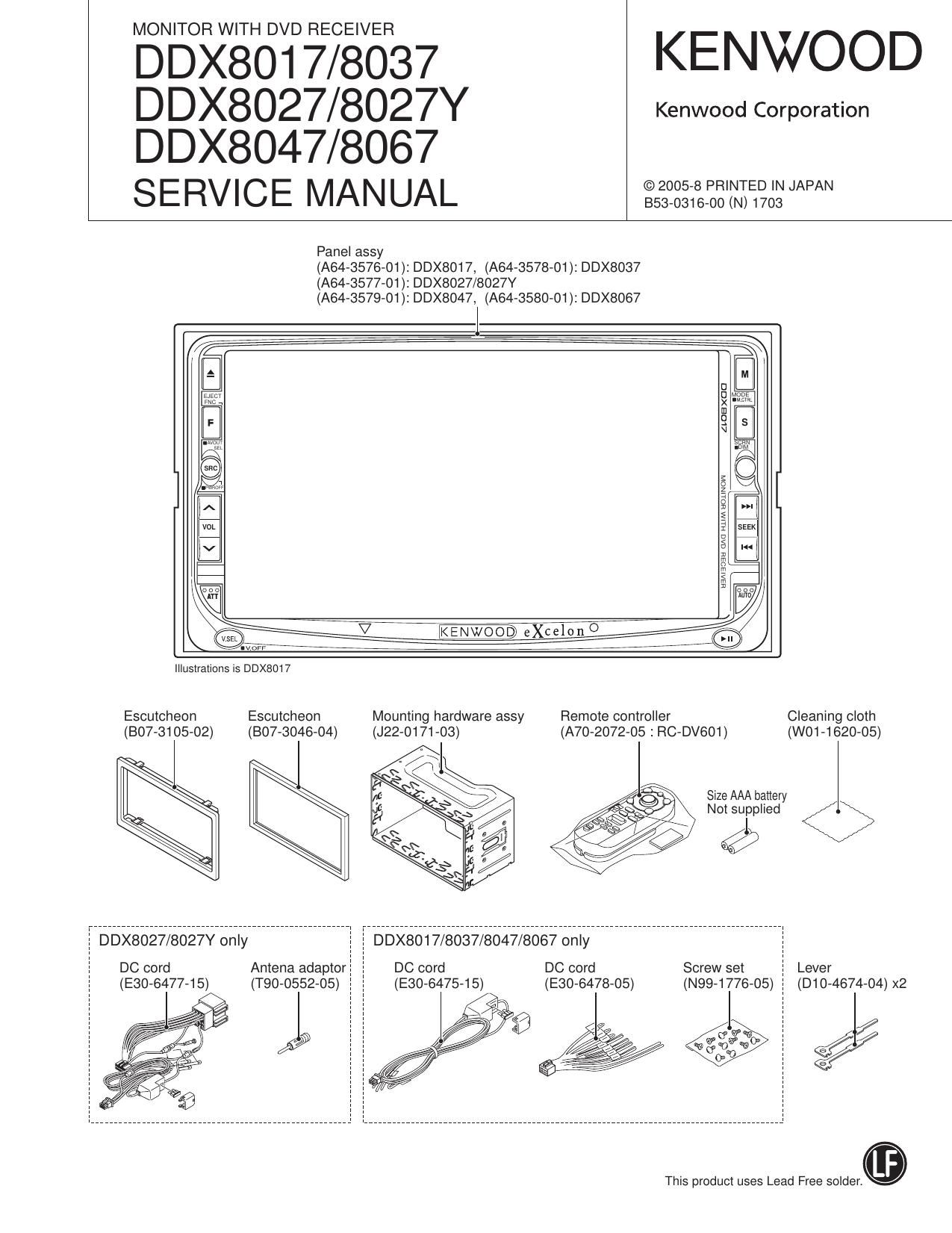
Kenwood DDX 8047 Service Manual
This is the 114 pages manual for Kenwood DDX 8047 Service Manual.
Read or download the pdf for free. If you want to contribute, please upload pdfs to audioservicemanuals.wetransfer.com.
Page: 1 / 114