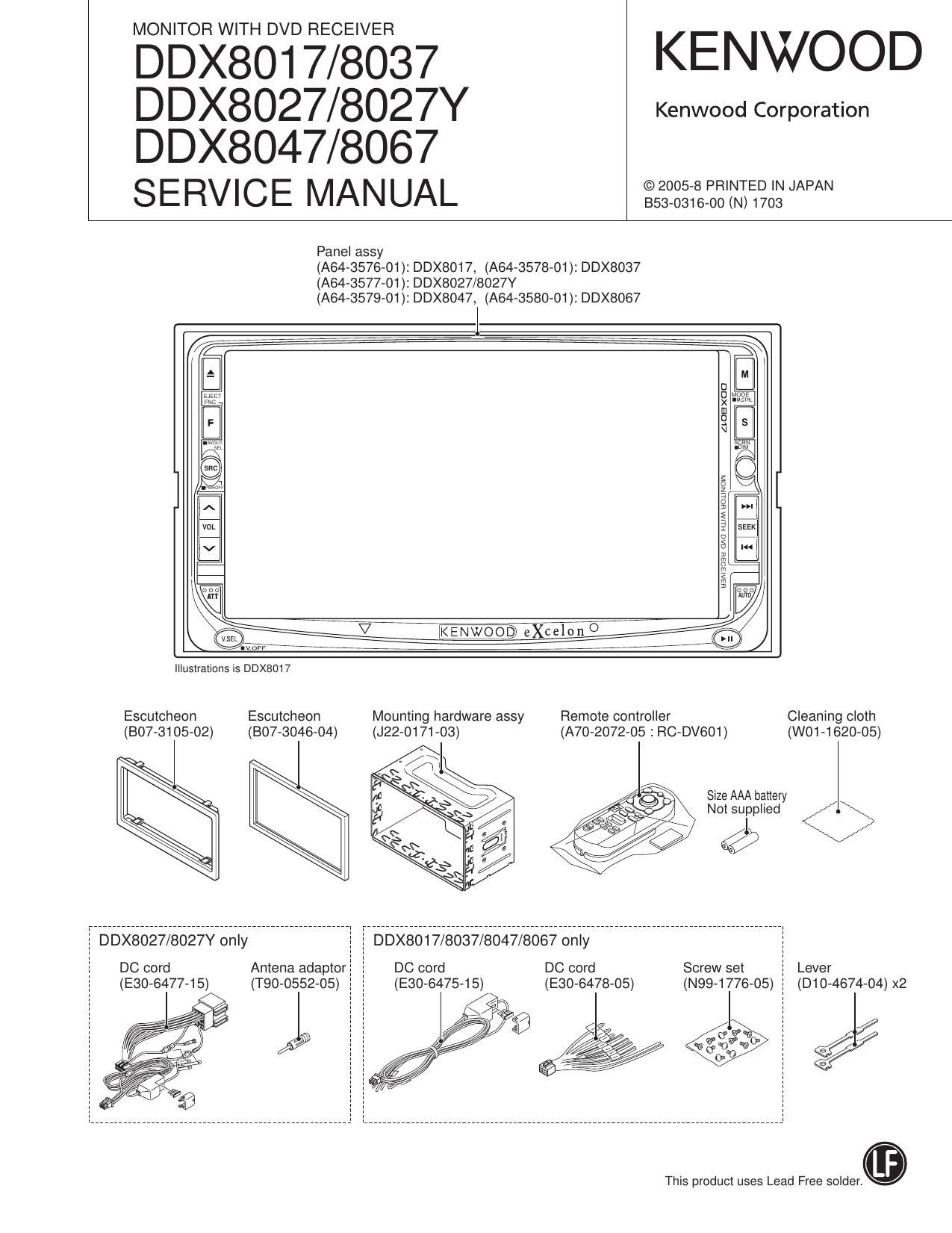
Kenwood DDX 8027 Y Service Manual

This is the 114 pages manual for Kenwood DDX 8027 Y Service Manual.
Read or download the pdf for free. If you want to contribute, please mail your pdfs to info@audioservicemanuals.com.

Page: 1 / 114
left right
Kenwood DDX 8027 Y Service Manual

Extracted text from Kenwood DDX 8027 Y Service Manual (Ocr-read)


Page 2

DDX8017/8027/8027Y
DDX8037/8047/8067

NOTES ON ASSEMBLING THE MECHANISM

1. Fasten Screw A so that the interval (a) will be about 5.2mm
and the interval (b) will be about 2.6mm (The interval (a)
can be measured using a pair of vernier calipers or similar
tools.)

2. Turn B so that Position (0) will come at about the center of
interval (d).

3. Then, play the test disc and fine tune A or B so that the jitter
value would be minimized.

Page 12

DDX8017/8027/8027Y
DDX8037/8047/8067

12

COMPONENTS DESCRIPTION

Ref. No. Application] Function Operation] Condition] Compatibility
IC413 Logic lC (Multiplexer) For audio signal selection (For MAIN source)
|C414 Logic IC (Multiplexer) For audio signal selection (For 2-ZONE sources)
|C415 Video switch Video signal selection (For monitoring main unit)
IC416 Video switch Video signal selection (For AVOUT)
ICSOO Isolation amplifier IC For audio signal GND isolation (LX)
|C501 Logic lC (Inverter) For reversing resetting signal
ICSO2 Logic IC (Buffer) Buffer for remote control signal for NAVI
Q6 ANT-CONT SW Comes on when TUNER source is selected
Q7 P-CONT SW Goes OFF when STANDBY source is selected
Q8~10 For P-CONT circuit control Controlling P-CONT circuit
Q11 For P-CONT circuit control Controlling P-CONT circuit
Q12 BU detection SW Comes ON power supply voltage is about 8.8V or more
Q13 For EXT-AMP control Control of external amplifier
Q14 For surge voltage detection Comes ON when Q15 is ON
Q15 For surge voltage detection Comes ON when power supply voltage is about 20V or more
Q50 For i9V power supply Comes ON when 051 is ON
Q51 For i9V power supply Comes ON when SW14V is ON
052 SW14V power supply SW Comes on at P-ON
Q54 For BU5V power supply
055 A8V oversupply SW Comes ON when SW14V is ON
Q58 For BU5V power supply
Q59 A8V power supply BU14V A 8V for audio is supplied
Q61 V5V power supply SW Comes ON when SW14V is ON
062 SW5V power supply SW Comes ON at P-ON
Q63 For SW5V power supply BU5V ~> SW5V is supplied
Q64 For V5V power supply BU14V a 5V for video is supplied
Q65~70 For i9V power supply
@150 SVRS'BV aUdio 3'3V' Comes ON when sw14v is ON
ICtSO power supply SW
0151 For SVFl voltage reduction control Electric current control of SVFl voltage reduction circuit
Q152 SVFl6.8V, audio 3.3V, |C150 power supply Power supply to |C150, voltage supply to 0151
Q200 For audio muting Audio muting of pre-out front right channel
0201 For audio muting Audio muting of pre-out front left channel
Q202 For audio muting Audio muting of pre-out rear left channel
0203 For audio muting Muting at momentary power down, resetting, and audio mute timing
Q204 For audio muting Audio muting of pre-out rear right channel
Q205 For audio muting Audio muting of pre-out center channel
Q206 For audio muting Audio muting of pre-out sub-woofer channel
Q207 For audio muting Audio muting of AVOUT right channel
Q208 For audio muting Muting at momentary power down, resetting, and audio mute timing

Page 17

DDX8017/8027/8027Y

DDX8037/8047/8067
MICROCOMPUTERS TERMINAL DESCRIPTION

Pin No. Pin Name Module (physical) l/O Application Processing Operation Description
74 OPENicLOSEsOPENicLOSE PANEL | OPEN7CLOSE key (1 DIN) L: ON

74 OPENiCLOSE/EJECT PANEL | Tilt mechanism OPEN/CLOSE and eject (2DIN) L: ON

75 SRC PANEL | Source key L: ON

76 EJECT PANEL | Eject key (1 DIN) L: ON 2D|N Hl-fixed input
77 MINLPON PANEL 0 MINI liquid crystal Power supply control H: ON, L: OFF

78 DSI PANEL O DSI control (1 DIN)

79 lLLiDET Power supply I ILLUMI detection H: Normal, L: Detect
80 PAKiDET Power supply | Parking detection H: Normal, L: Detect
81 REViDET Power supply | Reverse detection H: Normal, L: Detect
82~84 NC 0

85 SHilNl SH-3 O (GRAPHIC)

86 SHisTBY SH-3 | (GRAPHIC)

87 SHisREQ SH-3 | Request from SH-3 p-com (GRAPHIC)

88 SHiMREQ SH-3 0 Request to SH-3 p-com (GRAPHIC)

89 SHiCON SH-3 O (GRAPHIC)

90 SHiRST SH-3 o SH-a u-com resetting (GRAPHIC)

91 TOUCH SH-S | (GRAPHIC)

92 TOUCHiEN SH-3 O (GRAPHIC)

93 NAVLL VIDEO 0 L: NAVI, H: OTHER
94~97 TYPEO~TYPE3 EXTRA | Destination setting Refer to destination setting
98 SUBLEDioFF Other X35 0 2D|N disc LED control (2DIN)

99 TMOTOFLM 1D|N7MECHA 0 Monitor mechanism tilt control (1 DIN)

99 TlLTiUP 2D|N7MECHA O Tilt mechanism control (2DIN)

100 TMOTORiP 1D|N7MECHA 0 Monitor mechanism tilt control (1 DIN)

100 TILTiDOWN 2D|N7MECHA O Tilt mechanism tilt control (2DIN)

101 SMOTORiM 1D|N7MECHA 0 Monitor mechanism slide control (1 DIN)

102 SMOTORiP 1D|N7MECHA 0 Monitor mechanism slide control (1 DIN)

103 BVSS

104 BVDD

105 SW7A 1D|N7MECHA | Monitor mechanism detection(1 DIN) 2D|N is OUT

106 SW7B 1D|N7MECHA | (1 DIN) 2D|N is OUT

107 SW70 1D|N7MECHA | Monitor mechanism detection 2D|N is OUT

108 SW7D 1D|N7MECHA | Monitor mechanism detection 2D|N is OUT

109 ENABLE INVERTER O Backlight ON/OFF control H: ON

1 10 FLMD1 pCOM |

111 Y0 Touch panel 0 Touch panel control (OSD)

112 X1 Touch panel 0 Touch panel control (OSD)

113 X0 Touch panel 0 Touch panel control (OSD)

114~117 HPOS1~HPOS4 LCD 0 Display position control

118~120 MODE1~MODE3 LCD 0 Aspect setting

121 MIRROR LCD 0 Rear monitor mirror control

17

Page 32

DDX8017/8027/8027Y
DDX8037/8047/8067

32

TEST MODE

0 Mini Liquid Crystal
- When starting up in the Test Mode, all lights will be lighted.
- All lighted condition will be released by Disp key.

0 Key
- Tact Key specifications are shown below
1D|N (UNIT SP) IDIN (BOX SP) 2DIN
SRC As usual As usual As usual
VoIUp As usual As usual As usual
VolDw As usual As usual As usual
Track (Seek) Up As usual As usual As usual
Track (Seek) Dw As usual As usual As usual

Play/Pause - - Motor driver

AUTO (Tl/DISP) Short: NAVI forced interruption Motor driver NAVI forced interruption
Without mini liquid crystal Long: Motor

ATT As usual Flicker adjustment As usual

Screen As usua As usual As usual

Mode As usua As usual As usual

V.SEL V.SEL+AVOUT V.SEL+AVOUT V.SEL+AVOUT

FNC Normal (No Easy) Normal (NO Easy) Normal (NO Easy)
Eject As usual As usual As usual

0 Remote Controller

- Using NA-Fl300 (SW: AUD), the following operations will be conducted (Normal operation other than the following)

Key code Item
Direct Chroma IC adjustment mode ON/OFF (Write)
Band (FM+) Video mode switching (NAVI/AVIN/DVD)
M/S (AM-) DVD audio/Video confirmation switching

Performance (Play/Pause) Chroma setting value set/release

Tenkey 7 To previous item of chroma adjustment
Tenkey 8 Chroma setting value change (UP)
Tenkey 9 To next item of chroma adjustment
Tenkey 0 Chroma setting value change (DW)

Tenkey 1 Preset 1) DVD 5.1ch audio confirmation switching (DVD source only)

Tenkey 2 Preset 2) DC Offset detection check direct switching (CD-CH source only)

Tenkey 3 Preset 3) V-lN mirror mode switching

(
(
(
(

Tenkey 4 Preset 4) HPOSI DVD confirmation direct switching