Kenwood DDX 712 HU Service Manual

This is the 110 pages manual for Kenwood DDX 712 HU Service Manual.
Read or download the pdf for free. If you want to contribute, please mail your pdfs to info@audioservicemanuals.com.

Page: 1 / 110
left right
Kenwood DDX 712 HU Service Manual

Extracted text from Kenwood DDX 712 HU Service Manual (Ocr-read)


Page 1

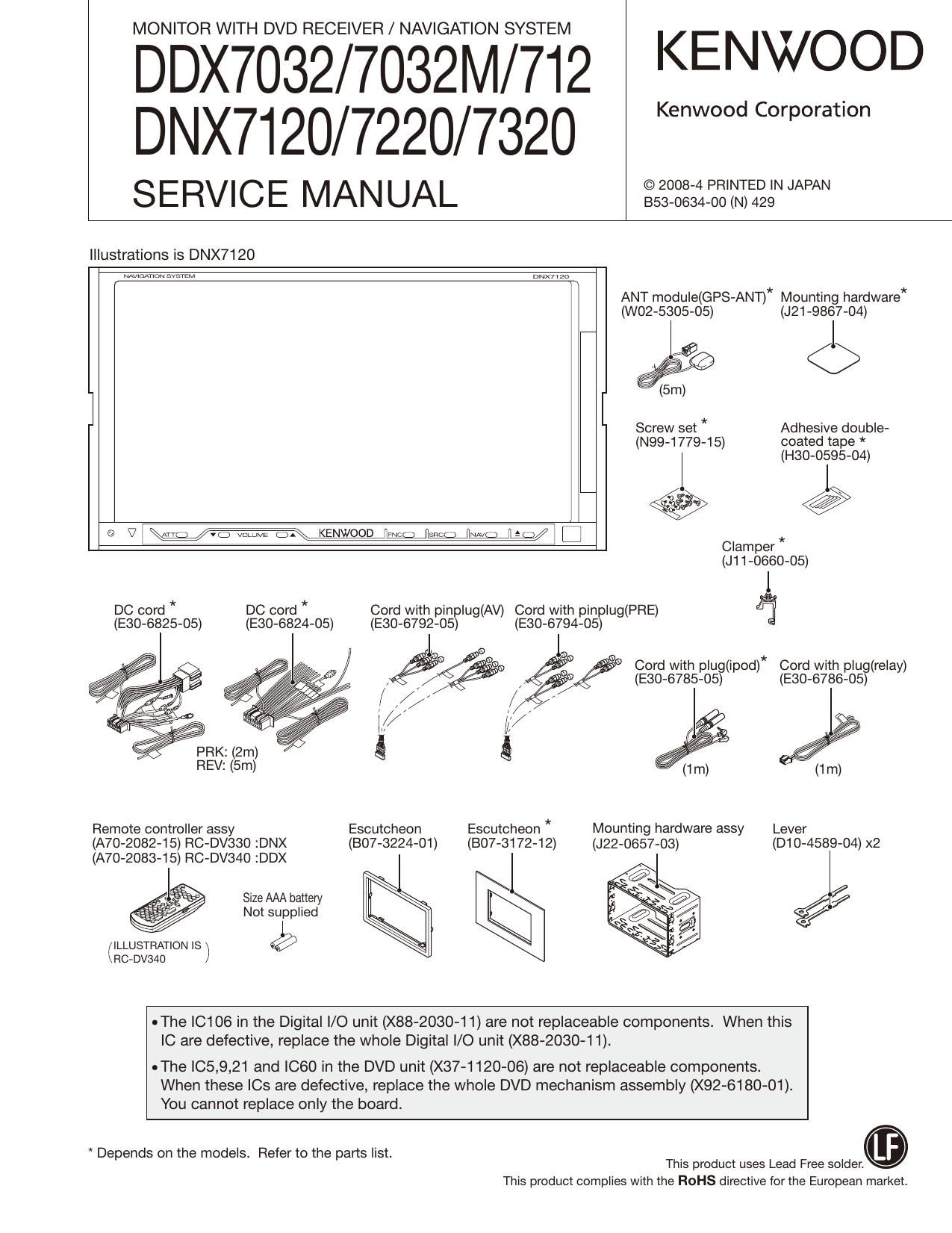
MONITOR WITH DVD RECEIVER / NAVIGATION SYSTEM

DDX7032/7032M/712 KENWQOD
DNX7120/7220/7320

SERVICE MANUAL aegggzzz'iiagym

Illustrations is DNX7120

DNX71 za

ANT module(GPS-ANT)* Mounting hardware*
(woz-ssos-os) (J21-9867-04)

Screw set * Adhesive double-
(N99-1779-15) coated tape *
(H30-0595-04)

" v W

@ V I \mg mvomm KENWOOD we 5n; W M I C]

Clam per *
(J11-0660-05)

DC cord * DC cord * Cord with pinplug(AV) Cord with pinplug(PRE) %
(E30-6825-05) (E30-6824-05) (E30-6792-05) (E30-6794-05)

PRK: (2m) Q g

Cord with plug(ipod)* Cord with plug(relay)
(E30-6785-05) (E30-6786-05)

REV: (5m) (1m)
Remote controller assy Escutcheon Escutcheon * Mounting hardware assy Lever
(A70-2082-15) RC-DV330 :DNX (B07-3224-01) (BO7-3172-12) (J22-0657-03) (D10-4589-04) x2

(A70-2083-15) RC-DV340 :DDX

l = Size AAA battery
. Not supplied
(ILLUSTRATION IS ) @

sf

RCeDVSAU

oThe IC106 in the Digital I/O unit (X88-2030-1 1) are not replaceable components. When this
IC are defective, replace the whole Digital l/O unit (X88-2030-11).

uThe |05,9,21 and ICGO in the DVD unit (X37-1120-06) are not replaceable components.

When these ICs are defective, replace the whole DVD mechanism assembly (X92-6180-01).
You cannot replace only the board.

* Depends on the models. Refer to the parts list. _
This product uses Lead Free solder.

This product complies with the ROHS directive for the European market.

Page 8

DDX7032/7032M/712
DNX7120/7220/7320

COMPONENTS DESCRIPTION

Ref. No. Application / Function Operation / Condition / Compatibility
|C701 Voltage detection lC u-com reset voltage (35V) monitoring
|C702 Pin100 u-com Mainly control Audio board
|C704 Power IC Power amplifier for speaker output
|C705 3-terminal regulator DSP7D5V circuit
Q1,2 Transistor P,CON output circuit
Q3 Transistor Reverse detection circuit
Q4 Transistor P,CON output circuit
Q5 Transistor Parking detection circuit
QB Transistor P,CON output circuit
Q7 Transistor ANT,CON output Circuit
Q8 Transistor ILLUMI detection circuit
QS Transistor ANT,CON output Circuit
Q10 Transistor BU detection circuit
Q11 Transistor EXTiCONT output circuit
Q13 Transistor SURGE detection circuit
Q14 Transistor ACC detection circuit
Q100 Transistor DSP7A5V circuit
Q101 Transistor PW-IC midpoint circuit
Q102 Transistor DSP7A5V circuit
Q103 Transistor PW-IC midpoint circuit
Q104 Transistor T8V circuit (E-TYPE ONLY)

Q105 Transistor BU5V circuit

Q106 Transistor PW-IC midpoint circuit

Q107 Transistor T8V circuit (E-TYPE ONLY)

Q108 Transistor BU5V Circuit

0109,110 Transistor PW-IC midpoint circuit

Q111,112 Transistor SW5V circuit

Q113,114 Transistor S|R78W14V circuit (K/R-TYPE ONLY)
Q115,116 Transistor ASV circuit

Q117 Transistor SIR,SW14V circuit (K/R-TYPE ONLY)
Q118 Transistor A8V circuit

Q119 Transistor SIR,SW14V circuit (K/R-TYPE ONLY)
Q120~122 Transistor DSPiDSV Circuit

QSOO~302 Transistor ADCiMUTE circuit

Q500,501 Transistor On during AM (Tuner8V)

0650,651 Transistor SATiRX SW circuit

0652 Transistor SIRIUsiDET SW Circuit

Q700 Transistor RESET detection circuit

Q701 Transistor DET MUTE circuit (Trigger Reset)
Q702 Transistor Video signal detection circuit (AV selector a u-com)
Q703 Transistor AV selector control RESET circuit
Q704 Transistor DET MUTE circuit (Trigger Reset)
Q705 Transistor AV selector control circuit

Page 13

DDX7032/ 7032 M/712
DNX7120/7220/ 7320

MICROCOMPUTERS TERMINAL DESCRIPTION

Pin No. Pin Name l/O Application T122326 Processing Operation Description
91 VCC2 -
92 PON 0 Power ON/OFF control H: Power ON
93 V88 -
94 MCNT 0 Switching of tilt mechanism power supply voltage H: 8V, L: 5V
95 JIGU7EJ l Operable without tilt mechanism
96-99 NC 0 NC Not used
100 WRT7E2P | Used for writing data in E2P H: E2P access, L: Normal
101 NC 0 NC Not used
102 VD | For VCOM adjustment
103,104 NC 0 NC Not used
105 EJ EGT | Eject key
106,107 NC 0 NC Not used
108 INV,SW 0 Switching of Inverter free run frequency
109 ENABLE 0 Back light ON/OFF H: ON, L: OFF
110 WRTiTC I Used to update T/C H: T/C access, L: Normal
111~113 NC 0 NC Not used
114 TYPE1 l Destination setting (1)
115 TYPE2 1 Destination setting (i)
116 TYPE3 1 Destination setting 0
117-121 NC 0 NC Not used
122 TYPEO | Destination setting 1)
123 TciRESET 0 Reset of T/C
124 NTiPALilN | NTSC/PAL identification input H: NTSC, L: PAL
125 VMUTE O VMUTE of X35 H: MUTE ON
126 MSTiWAlT l MST WAIT request
127 TC,R | For RGB auto adjustment Not used
128 TC,G | For RGB auto adjustment Not used
129 TC,B I For RGB auto adjustment Not used
130 VSS -
131 VCOM i For y curve auto adjustment / DEF.2t8V
132 VCC1 -
133-135 NC 0 NC Not used
136 KEYS | Key
137 XDATA | Touch data input
138 YDATA | Touch data input
139 RisENS | Panel mechanism tilt detection
140 AVSS -
141 AiREMO 1 Analog remote controller for Matsuda Not used
142 VREF |
143 AVCC -
144 AVSCL/TC 0 Communication clock with AV SW T/C and E2P
SCL/E2P780L ' I

13

Page 20

DDX7032/7032M/712
DNX7120/7220/7320

MICROCOMPUTERS TERMINAL DESCRIPTION

Pin No. Pin Name l/O Application T123216 Processing Operation Description
D6 EPiMREQ | SysCom communication request
D7 DA28 I/O Data bus
D8 #EPilNl | Reset start notification
D9 AD16 0 Address bus
D10 MDC O (ETHER |/F for design)
D11 RXERR | (ETHER I/F for design)
D12 MIITXDS O (ETHER I/F for design)
D13 IPODiBSY | iPod READY/BUSY L: BUSY, H: READY
D14 LOWjMID | Setup of destination H: LOW model, L: MID model
D15 BTiRESET 0 BT reset
D16,17 NC
E1 #SDCSZ O SDRAM chip select
E2 #SDWE O SDRAM write enable
E3 DA22 l/O Data bus
E4 ADS 0 Address bus
E5 DA15 I/O Data bus
E6 AD21 0 Address bus
E7 DA17 l/O Data bus
E8-1 O VDD R
E11 MIIRXDO | (ETHER I/F for design)
E12 TXERR O (ETHER |/F for design)
E13 EP,CON | Permission to operate PE9307
E14 USBLERR | 5V over current detection in USB1 L: Over current is detected.
E15 USBLEN 0 Control of USB1 5V over current detection 10 L: USBSV OFF, H: USBSV ON
E16,17 NC
F1 #RAS O SDRAM RAS
F2 #SDCS1 O SDRAM chip select
F3 #SDCSO O SDRAM chip select
F4 #DQMS 0 Memory data mask
F5 ABS 0 Address bus
F6-8 GND R
F9,10 VDD C
F1 1 GND R
F12 EPiBUDET | Momentary power down notification L: Normal operation
H: Momentary power down detection
F13 NC
F14 ADC,GND
F15 lPODiRESET (NC) 0 Authentication chip reset control (Not used)
F16,17 NC
G1 #DQMO 0 Memory data mask
G2 #CAS 0 SDRAM CAS
G3 DA21 I/O Data bus
G4 AD22 0 Address bus
GS VDD R

20

Page 108

DDX7032/7032M/712
DNX7120/7220/7320

SPECIFICATIONS (K/R TYPE)

Monitor section
Picture Size .. 6.95 inches (diagonal) wide
.. 156.2 mm (W) x 82.4 mm (H)
.. Transparent TN LCD panel
.TFT active matrix system
336,960 (480H x 234V x RGB)
........................ 99.99 %
...RGB striped arrangement
Cold Cathode Fluorescent Tube


Display System
Drive System
Number of Pixels
Effective Pixels
Pixel Arrangement ..
Back Lighting .....

DVD player section
D/A Converter..
Audio Decoder

............ Linear PCM/ Dolby Digital/ dts/ MP3/ WMA/ AAC

..24 bit

Video Decoder .................... MPEG1/ MPEGZ/ MPEG4 (DivX)
Wow & Flutter .................................. Below Measurable Limit
Frequency Response
Sampling frequency; 96 kHz.. .20 - 44,000 Hz
Sampling frequency; 48 kHz.. .20 - 22,000 Hz
Sampling frequency; 44.1 kHz.. ....20 - 20,000 Hz

Total Harmonic Distortion ..............
S/N Ratio (dB) .....
Dynamic Range ..

.. 0.008 % (1 kHz)
.. 98 dB (DVD-Video 96 kHz)
. 98 dB (DVD-Video 96 kHz)

Disc Format ............... DVD-Video/ VlDEO-CD/ CD-DA
Sampling Frequency. ........................ 44.1/ 48/ 96 kHz
Quantifying Bit Number .................................... 16/ 20/ 24 bit

USB interface section

USB Standard ................................................... USB 1.1/ 2.0
File System .................................... .FAT 16/ 32
Maximum Power Supply Current .. ..... 500 mA
D/A Converter ....................... 24 Bit
Audio Decoder MP3/ WMA/ AAC

FM tuner section
Frequency Range (200 kHz) .......
Usable Sensitivity (S/N : 30 dB) .
Quieting Sensitivity (S/N : 50 dB) ..
Frequency Response (x 3.0 dB)....
S/N Ratio (dB) ............

.87.9 MHz - 107.9 MHz
9.3 dBf (0.8 pV/ 75 o)
. 15.2 dBf(1.6 pV/ 75 o)
.............. 30 Hz - 15 kHz
.70 dB (MONO)

Selectivity (1 400 kHz).. ............ Z 80 dB
Stereo Separation ............................................. 40 dB (1 kHz)
AM tuner section

Frequency Range (10 kHz) ..................... 530 kHz - 1700 kHz
Usable Sensitivity ....................................................... 28 dBp

Video section

Color System of External Video Input .......................... NTSC
External Video Input Level (mini jack) ......... 1 Vp-p/ 75 Q
External Audio Max Input Level (mini jack) ....2 V/ 25 k9

108

Video Output Level (RCA jacks) .. .. 1 Vp-p/ 75 0
Audio Output Level (RCA jacks) .. 1.2 V/ 10 km
Analog RGB input (DDX712/DDX7032 only) .. 0.7 Vp-p/ 75 D

Audio section
Maximum Power (Front & Rear) ..
Full Bandwidth Power (Front & Rear)
(4 0, 14.4 V, 1 % THD)
Preout Level (V)
Preout Impedance
Speaker Impedance

Tone action
Bass ............................................................ 100 Hz : 8 dB
Middle. ..1 kHz:8dB
Treble .. 10 kHz : 8 dB
External SW
Maximum Power Supply Current .............................. 500 mA
Navigation section (DNX7120 only)
Receiver ................................... High-sensitivity GPS receiver
Reception Frequency ..................... 1575.42 MHz (C/A code)
Acquisition Times
Cold .............. .< 38 seconds

Factory Reset .< 45 seconds
(On average for a stationary receiver with a clear view of

the sky)
Accuracy

Position ............................................... < 10 meters typical

Velocity .......... ..0.05 m/sec. RMS
Position Method .................. GPS
Antenna .............................................. External GPS antenna
General
Operating voltage ....................... 14.4 V (11 - 16 V allowable)
Current Consumption ............................... 15 A

Dimensions(W>

............................................ 7-3/16 x 4-7/16 x 6-7/16 inch
Operational Temperature Range .................. -10 °C - +60 °C
Storage Temperature Range -20 °C - +85 °C
Weight (DNX7120) ................ .. 2.5 kg (5.5 lbs)
Weight (DDX712/DDX7032) .......................... 2.45 kg (5.4 lbs)

KENWOOD follows a policy of continuous advancements
in development. For this reason specifications may be
changed without notice.

US and foreign patents licensed from Dolby Laboratories.
Although the effective pixels for the liquid crystal panel is
given as 99.99% or more, 0.01% of pixels may not light or
may light incorrectly.