Kenwood DDX 7032 HU Service Manual

This is the 110 pages manual for Kenwood DDX 7032 HU Service Manual.
Read or download the pdf for free. If you want to contribute, please mail your pdfs to info@audioservicemanuals.com.

Page: 1 / 110
left right
Kenwood DDX 7032 HU Service Manual

Extracted text from Kenwood DDX 7032 HU Service Manual (Ocr-read)


Page 1

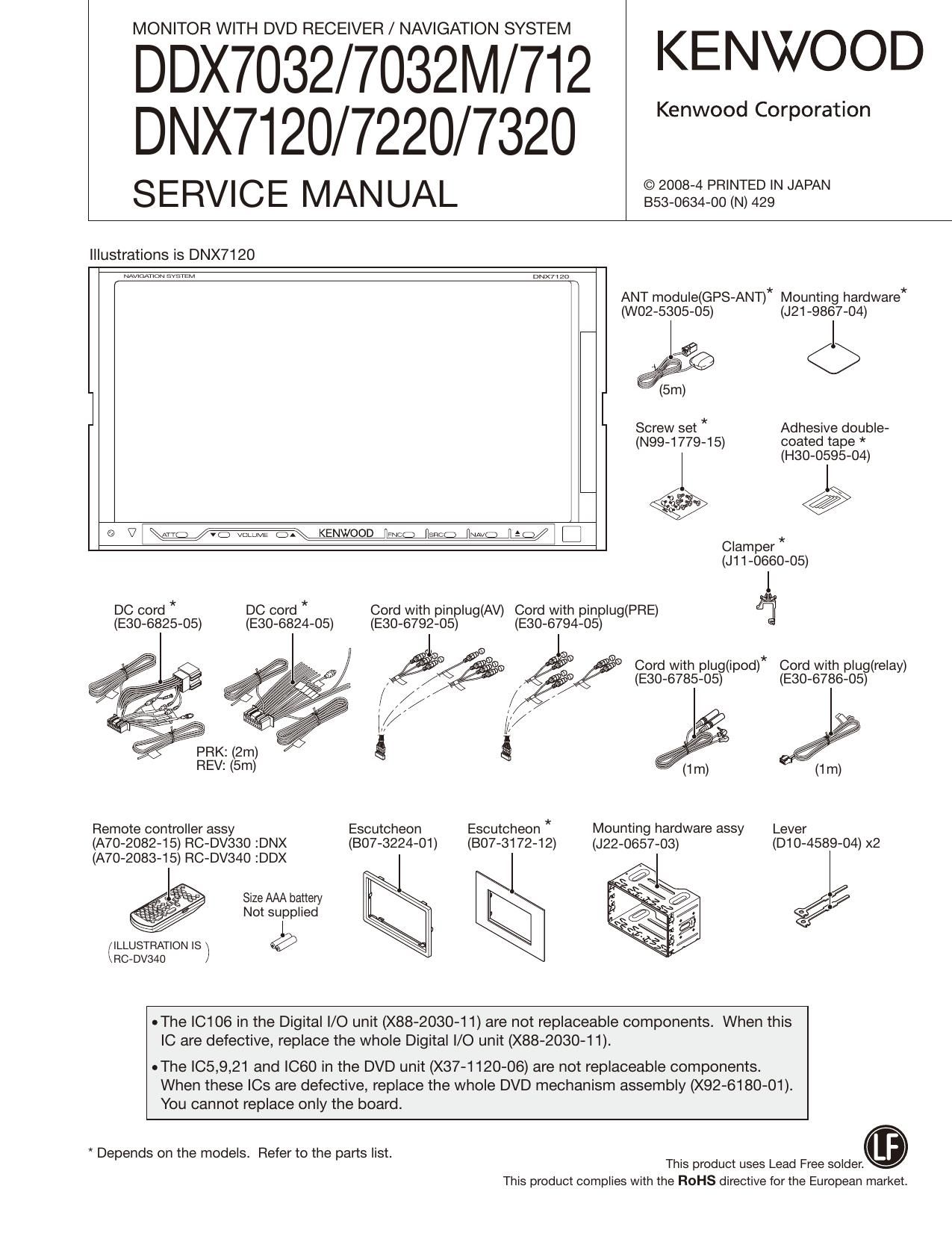
MONITOR WITH DVD RECEIVER / NAVIGATION SYSTEM

DDX7032/7032M/712 KENWQOD
DNX7120/7220/7320

SERVICE MANUAL aegggzzz'iiagym

Illustrations is DNX7120

DNX71 za

ANT module(GPS-ANT)* Mounting hardware*
(woz-ssos-os) (J21-9867-04)

Screw set * Adhesive double-
(N99-1779-15) coated tape *
(H30-0595-04)

" v W

@ V I \mg mvomm KENWOOD we 5n; W M I C]

Clam per *
(J11-0660-05)

DC cord * DC cord * Cord with pinplug(AV) Cord with pinplug(PRE) %
(E30-6825-05) (E30-6824-05) (E30-6792-05) (E30-6794-05)

PRK: (2m) Q g

Cord with plug(ipod)* Cord with plug(relay)
(E30-6785-05) (E30-6786-05)

REV: (5m) (1m)
Remote controller assy Escutcheon Escutcheon * Mounting hardware assy Lever
(A70-2082-15) RC-DV330 :DNX (B07-3224-01) (BO7-3172-12) (J22-0657-03) (D10-4589-04) x2

(A70-2083-15) RC-DV340 :DDX

l = Size AAA battery
. Not supplied
(ILLUSTRATION IS ) @

sf

RCeDVSAU

oThe IC106 in the Digital I/O unit (X88-2030-1 1) are not replaceable components. When this
IC are defective, replace the whole Digital l/O unit (X88-2030-11).

uThe |05,9,21 and ICGO in the DVD unit (X37-1120-06) are not replaceable components.

When these ICs are defective, replace the whole DVD mechanism assembly (X92-6180-01).
You cannot replace only the board.

* Depends on the models. Refer to the parts list. _
This product uses Lead Free solder.

This product complies with the ROHS directive for the European market.

Page 18

DDX7032/7032M/712

DNX7120/7220/7320

18

MICROCOMPUTERS TERMINAL DESCRIPTION

Truth value table
(D Destination setting

TYPEO Setup Voltage (Power supply voltage = 5)

MODEL Category Desm- TYPES TYPE2 TYPE1 TYPEO Settings for u-Com Acme Adua'
tion . pull down pull up re-
Destination . . . .
, . Mid pomt reSistance Sistance
K 0 O 1 min max
voltage (k0) (k9)
' ' ' ' ' K 0.00 0.00 0.62 10 None
DDX M/M2 0 O 1 E/E2 0.63 1.25 1.87 3.3 10
V 0 0 1 M/M2 1.88 2.50 3.12 10 10
R 0 0 1
Low V/X 3.13 3.75 4.37 30 10
K 0 1 1 R 4.38 5.00 None 10
E 0 1 1
DNX M 0 1 1
X 0 1 1 '
K 1 0 1
E/E2 1 0 1
DDX M/M2 1 O 1
X 1 O 1
R 1 O 1
Mid
K 1 1 1
E 1 1 1
DNX - - - - -
TYPEO is AD input.
Refer to the next table (TYPEO Setup Voltage) for ".
0 MEDIA MICROPROCESSOR: EP9307IRZ (X88: IC106)
_ _ _ _ True Value _ , _ .
Pin No. Pin Name l/O Application Table Processmg Operation Description
A1 #051 | Watchdog startup
A2 #037 | BOOT bus width select
A3 SDCLKEN O SDRAM clock enable
A4 DA31 l/O Data bus
A5 DA29 I/O Data bus
A6 DA27 l/O Data bus
A7 NC
A8 #RD 0 Memory read
A9 MllRXD3 | (ETHER I/F for design)
A10 RXDVAL | (ETHER I/F for design)
A11 MIITXD1 O (ETHER |/F for design)
A12 CRS | (ETHER |/F for design)
A13 NC

Page 32

DDX7032/7032M/712
DNX7120/7220/7320

TEST MODE

5.13. Flicker adjustment

@Use Tenkey 0 on the remote controller to turn the Flicker
adjustment On.

@Make the screen mode FULL, and set the monitor video
to VIDEO.

©Press Tenkey 0 on the remote controller during the flicker
adjustment to turn the adjustment Off.

@When the screen mode/monitor video has been changed
to Flicker adjustment, it shall be remained as it is after the
Flicker adjustment is turned Off.

5.14. Panel Mechanism
I Touch operations shall be available even when the Tilt
mechanism is in the Full Open condition.

5.15. Driver for Panel Mechanism Motor

I With the condition when [A'l'l'] key is pressed and hold,
the driver port for motor shall be turned On.

I While [Am key is being pressed, the motor is turned On
in reverse direction when the key is On for the first time
and the motor is stopped when the key is Off.

I With the key is pressed On for the second time, the motor
is tuned On in the normal (forward) direction, and the mo-
tor is stopped when the key is Off. Repeat the same steps
in the succeeding procedure.

5.16. Clearing E2PROM contents
I Clear the E2PROM contents which should not remain in it
when shipping the unit.
Clear the contents of E2PROM with [SRC] key + [FNC]
key + [Reset] key".
Clear OK: Turn off Sl. (Except SI, all of the others shall
be as they are in normal.)
Clear NG: Boot up normally.
The following information is cleared:
DC Offset information / Memory information / Retailer
mode information / Service information
I If a jig is connected and the region is written in, the follow-
ing information shall be cleared.
Serial No. / Security code / Touch correction / HPOSl
correction / Mechanism position adjustment
Mstar adjustment / DC Offset information / Memory
function / Retailer mode information / Service informa-
tion
Note: Since the above data is cleared (un-defined) when
the E2PROM has been replaced during the service, it
is required to readjust the data in the Test mode.

32

5.17. Security Code writing-in

I When entering the Security Code that is defined as a pair
of the serial number of the product (for other destinations
than K/R), use [Security Setup] key on the Setup screen to
call the Security screen.

I Only when the Security Code of E2PROM of the product
for other destinations than K/R is blank, [Set] key is shown
and press that key.

I In the Security Code Writing screen, run the same opera-
tion as when registering Security Code in normal mode,
and press the [Enter] key to start writing.

Note: The Security Code to be entered in the above step
is the set-specific code linked to the serial No.

I Writing of the code is successfully completed when
Complete" is displayed, and if NO" is displayed, the
writing the code is unsuccessfully completed.

Note: If NO" is displayed, transfer to the Test mode again
and repeat the above process from the 1st step.

5.18. Procedure to clear Security Code

I If the unit is started with the Security ON condition when
the destination is K/R, use the following procedure to
clear the Security Code (in the mode other than the Test

Mode).

@When the unit is Reset or is powered on after the back-
up OFF under the Security ON condition, the unit boots
up from the Security Code Entry screen.

@Select Audio SW mode on the remote controller, and
manually enter the code following the next procedure:

Step 1: Enter "K" (Press Tenkey5 twice)

Step 2: Enter "C" (Press Tenkey2 three times)

Step 3: Enter "A" (Press Tenkey2 once)

Step 4: Enter "R" (Press Tenkey7 three times)

Note: On the other remote controller than that pro-
vided as an accessory, enter R by pressing
Tenkey7 twice.

When the entry is made improperly during the Steps

1~4, repeat the code entry from the Step 1 after en-
tering other remote controller Key.

®When the Security Code Entry screen is cleared, the
Security Code clear is completed.

5.19. Other
I Do not operate the Back Up Memory function during the
Test mode.

Page 36

DDX7032/7032M/712
DNX7I20/7220/7320

ADJUSTMENT

@-2-2: DDX7NAV| KNA-GSZO Enlarge OK
Adjust the Screen Adjustment key so that the NAVI
screen becomes horizontally symmetrical.

MM

Tools Settings Volume


Adjust the key so that the width of the
left gap is same as that of right gap.

Enlarge OK

UDUDU

5; j; I» ljj W11 L'jij'iljl.
. lJ jjjlj ,jjjjijijllliljljlj

Enlarge NG

IIWWIEQfit

"1 Illi'UFil .

Enlarge OK

. Pixel Adjustment: PHASE
Adjust the Pixel Adjustment key so that the screen be-
comes gray.
OK

- Display Range Adjustment: FREQ
Adjust the Display Range Adjustment key so that there is
no vertical black stripes (blur) on the screen.

36