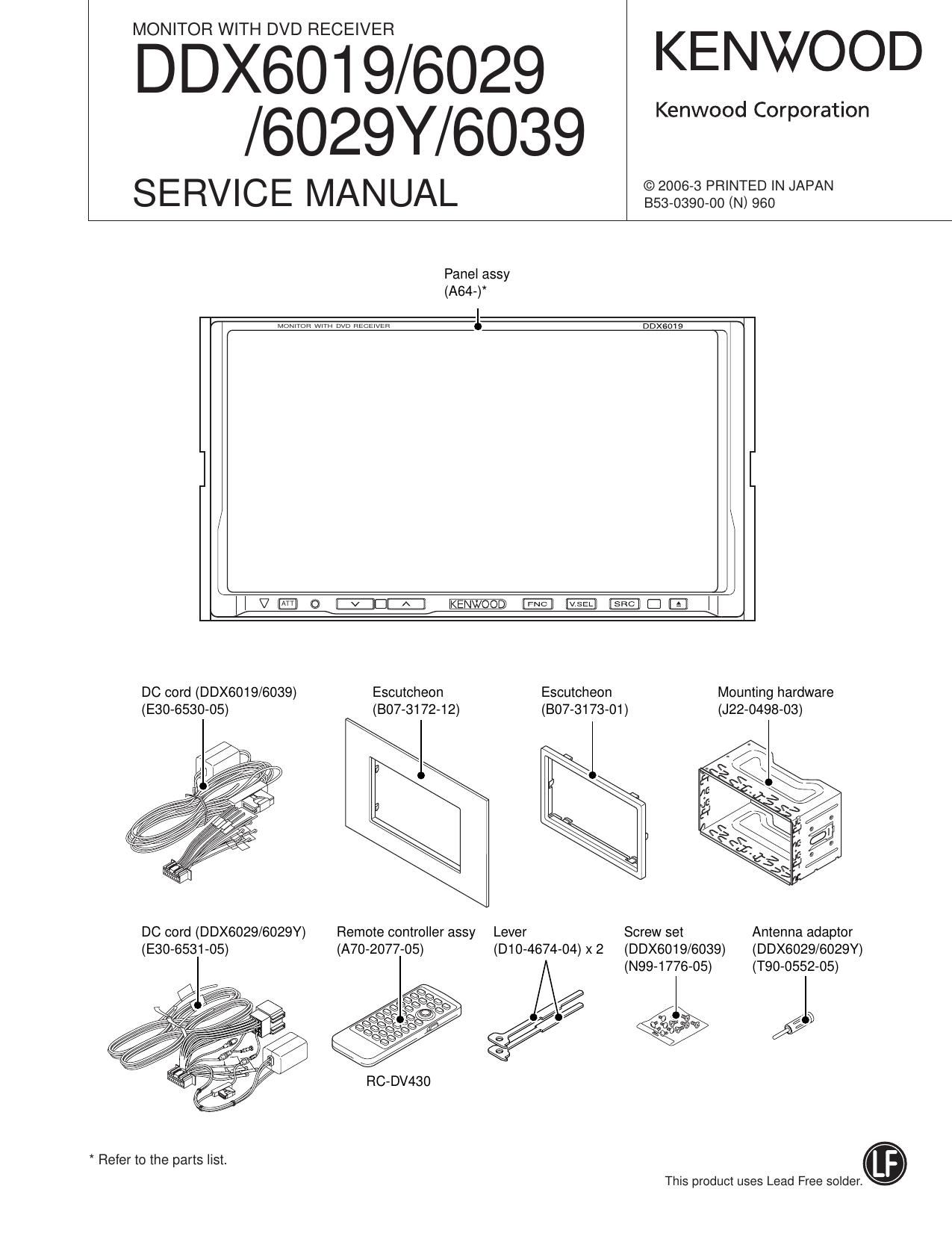
Kenwood DDX 6029 HU Service Manual

This is the 86 pages manual for Kenwood DDX 6029 HU Service Manual.
Read or download the pdf for free. If you want to contribute, please mail your pdfs to info@audioservicemanuals.com.

Page: 1 / 86
left right
Kenwood DDX 6029 HU Service Manual

Extracted text from Kenwood DDX 6029 HU Service Manual (Ocr-read)


Page 5

DDX6019/6029/6029Y/6039

COMPONENTS DESCRIPTION

Ref. No Application] Function Operation / Condition] Compatibility
0304 Transistor Pre-Out Mute (RL)
0305 Transistor Pre-Out Mute (RR)
0306 Transistor Pre-Out Mute (SUB L)
0307 Transistor Pre-Out Mute circuit (SUB)
0308 Transistor Pre-Out Mute (SUB Fl)
0309 Transistor Pre-Out Mute (AV-OUT L)
0310 Transistor Pre-Out Mute circuit (AV-OUT)
0311 Transistor Pre-Out Mute (AV-OUT Fl)
0 ELECTRIC UNIT (X34-439x-xx)
Ref. No Application I Function Operation] Condition] Compatibility
IC1,2 DC-DC control IC DC-DC circuit control/drive
|C3 5.0V 3 terminal regulator Power supply for 85.0V
IC4 5.0V 5 terminal regulator Power supply for D5.0V
ICS 3.3V 5 terminal regulator Power supply for D3.3V
IC80 3.3V 3 terminal regulator Power supply for BU3.3V
IC101 OSD ROM ROM for OSD display
IC102 OSD IC IC for OSD display
lCZtO Inverter For amplifying clock for OSD
ICZt1 AND HSYNC delay
IC301 AND 3.3V~>5.0V conversion
|C302 E2PROM Nonvolatile memory
IC303 RESET IC For SYSCOM reset
IC304 SYS uCOM System control
IC305 AND Remote control and wired remote control
IC401 OR Buffer for SPDIF
ICBOO DC-DC control IC DC-DC circuit control/drive
l0601 Schmitt trigger inverter Remote control waveform shaping
IC603 AND VSYNC delay
IC700 ISO AMP For TViFl, TViL
|C702 ISO AMP For AVIN17Fl, AV|N17L
IC703 AND Buffer for NAVLREMO
IC704 Motor driver For tilt mechanism
|C801 SW lor AVOUT Selection of TV, AVIN1, DVDIN
ICSOZ SW for VIN Selection of TV, AVIN1, DVDIN, BCAME, NAVISYNC
l0804 SW tor sync separation Selection of BCAME, AVIN1/AVIN2
IC805 Video SW Selection of TV Fl/G/B, NAVI Fl/G/B
l08t0 Driver 7552 driver and 6013 amplifier
lCStZ 5.0V 3 terminal regulator Power supply for SW5.0V

Page 6

DDX6019/6029/6029Y/6039
COMPONENTS DESCRIPTION

Ref. No Application] Function Operation] Condition] Compatibility
|C815 Sync separation IC Sync separation
035 Short detection circuit For SW5.0V
07,8 Short detection circuit For SW8.5V
060,61 SW For SW3.3V
0101 Emitter follower Current amplification and buffer for OSDiFl signal
0102 Emitter follower Current amplification and buffer tor OSDiG signal
0103 Emitter follower Current amplification and buffer for OSDiB signal
0105,106 Emitter follower Current amplification and buffer tor X357V|N
0301 SW For X347RST
0302 SW For KEYiRESET
0307,308 SW For SI
0404 Emitter follower Current amplification and buffer for DVSiDVDIN
0600,601 Short detection circuit For BL9.0V
0602,603 SW For KEYilLL
0800 Emitter follower Current amplification and buffer tor ROUT
0801 Emitter follower Current amplification and buffer for GOUT
0802 Emitter follower Current amplification and buffer for BOUT
0803 Emitter follower Current amplification and buffer tor VIN
0804 MUTE circuit For ROUT
0805 MUTE circuit For GOUT
0806 MUTE circuit For BOUT
0807 MUTE circuit Fleverse
0 VIDEO UNIT (X35-467x-xx)
Ref. No Application] Function Opeiationl Condition] Compatibility
|C1 AND IC3 VSYNC input signal buffer
|C2 NOT HSY signal reverse
IC3 Timing controller LCD drive timing control IC
IC4 LPF PLL circuit
IC5 Flip-flop HSY, VSY phase matching circuit
ICG 3 state bulfer HSY, VSY phase matching circuit
|C7 NAND 2/3 divided circuit
ICS NOR 2/3 divided circuit
ICQ 2-in-1 flip-flop 2/3 divided circuit
|C11 NOT 2/3 divided circuit
|C12 AND 2/3 divided circuit
|C13 OR 2/3 divided circuit
|C14 NOT 2/3 divided circuit
|C100 One shot Timing matching

Page 30

DDX6019/6029/6029Y/6039
ADJUSTMENT

30

0 Horizontal Display Start Position and
OSD Display Position Adjustment
While checking the screen, adjust on the touch panel.

- Screen adjustment key: H POSI -

Go to te next adjustment screen

N ext

E E
|:| III

I

Return to the menu screen
OSD adjustment key

Horizontal screen position adjustment

Screen adjustment key (HPOSI): The whole screen's hori-
zontal display starting position adjustment

OSD adjustment key: OSD only horizontal display starting
position adjustment

Image on the ad'ustment screen
DVD: Monoscope (TDV-540A, Title: 2, Chapter: 16)

TV: Monoscope
VlDEOt: Monoscope
Navigation: Input KNA-DV3200

NTSC area destination: NTSC video, PAL area destination:
PAL video are used.

TV tuner box suitable for each destination should be used.

" NAVI screen is the NAVI menu screen.

Ad'ustment procedure
1. On the test mode menu screen, press HPOSI.

2. Adjust the 5 types: Graphic, DVD, TV, VIDEO, Navigation
horizontal display starting positions.

3-1. Graphic:
Using the OSD key, adjust so that the background is not
shown on the both sides of the screen.
HPOSI key is not used. Please be careful not to touch this
key because this key is valid.

NG NG OK

3-2. DVD:
Insert TDV-540 disc, and after the air plane picture is dis-
played, press the remote control key (DVD mode) 4",
Monoscope is displayed.
At first, using the OSD key, adjust so that the background is
not shown on the both sides of the screen.
Then, using the screen adjustment key, adjust so that the
monoscope is symmetrical.

3-3.TV, VIDEO:
At first, using the OSD key, adjust so that the background is
not shown on the both sides of the screen.
Then, using the screen adjustment key, adjust so that the
monoscope is symmetrical.

3-4. NAVI:
At first, using the OSD key, adjust so that the background is
not shown on the both sides of the screen.
Then, using the screen adjustment key, adjust so that the
NAVI menu screen is symmetrical.

Right/Leftsymmetry

lllll llllll
lllll ll lllilll

f ¢ \dk/

NG NG

l l

After adjustment, press the Next key, and if Hposi OK" is
displayed, adjustment is completed.

Note:

When adjusting horizontal display starting position, when
not displayed exactly at the center (leaned toward left when
moved 1 step toward left, and leaned toward right when
moved 1 step toward right), place at the position closest to
the center but leaned toward the right, and press NEXT to
finalize (The screen is leaned toward the right by t or 2
dots).

Page 53

331/ as
90

new
war lDK

. ovs BE RST


DDX6019/6029/6029Y/6039

w

R3311 07K

CAUTION : For continued safety, replace safety
critical components only with manufacturers recom-
mended parts (refer to parts list).

A Indicates safety critical components. To reduce
the risk of electric shock, leakage-current or resis-
tance measurements shall be carried out (exposed
parts are acceptably insulated from the supply cir-
cuit) before the appliance is returned to the cus-
tomer.

Bua 3w

- DC voltages are as measured with a high imped-
ance voltmeter. Values may vary slightly due to

variations between individual instruments or/and

) s amass?» In
2 2 mar: 5:930 opuuwwfigfi $222
93 2331565
@®®@®@e @@»@ aIgs 111211n98®856 _I
I N m s s s 2 H I-o-I I-l-I
seas: EEEEEEE 32% game m I
EEEEE3*F IIIHEEE *EEEE s |
§UmomEDZZZE éa * CE
7 7 kV-j T a v I B
3 5 s a s s a I
T 1 1 1 I T 1 I
* R525 > | DTA144EUA
° DTC114YUA
-._, | 2SA1576A
3 |
WWI |
WWI
c310 55
L m | 2881188
inn I
,s ;% *5»
' ' D301 I
s
0307 0308 I E
" c
| 8
W | DTC323TU
| 28C4081
I
I44 W |
I43 W m |
I42 3W Haasmo |
m ItI 3W Rsssma W |
ta
me :39: |
I35 W R3790 W |
W137 W Ragsma W | DTA114EUA
I35 W R3971aa 35y DTA124EUA
I35, I DTC114EUA
5:: | DTC123JUA
W | DTC124EUA
4 l I DTC143EUA
mm
30M I DTC144EUA
25v I OUT
Im
Im |
Izsy
El TYPE) 12»- I IN
a I I2
1 0 I2 I GND
I I IzIy |
a a W
1 1 |
IIW
IIW |
Her I

units.

DDX6019/6029/5029Y/6039 (2/4)

X34-439x-xx A/2 (4/4) 53

Page 85

DDX6019/6029/6029Y/6039
PARTS LIST

DAUGHTER UNIT (X89-2882-71)

A N . . Desti- A N . . Desti-
Ret. No. g vev Parts No. Description nation Ret. No. g vev Parts No. Description nation
S178 5700919705 TACT SWITCH 58 2B J1 170654713 CLAMPER
59 1A J2270042r12 MOUNTING HARDWARE
D8 AVRM1608120M6A VARISTOR 60 1B J2270043712 MOUNTING HARDWARE
D1017 AVRM1608120M6A VARISTOR 61 3B J2270044703 MOUNTING HARDWARE
IC1 >I< GP1USS01XP ANALOGUE IC 62 1A J2270103723 MOUNTING HARDWARE ASSY
DVD MECHANISM ASSY (X92-5430-00) (DVS-7600V) 63 25 mm 7714 MOUNTING HARDWARE
1 1B A1075084r31 CHASSIS 64 1A 119071066741 GUIDE
2 28 A1075083721 CHASSIS ASSY 65 1B 49071057713 GUIDE
3 3A A1171650701 SUB CHASSIS 66 1B 09071087732 GUIDE
67 1B 119071088732 GUIDE
4 1B D1074763732 ARM
5 1B D1074764r23 ARM A 2A N0976143705 MACHINE SCREW
7 2B D1074768712 SLIDER 8 1A N0976144705 MACHINE SCREW
8 2B D10»4769703 SLIDER C 3B N0976145705 MACHINE SCREW
9 2A D1074771702 SLIDER D 3B N0976156705 MACHINE SCREW (M1 .4X1.6)
E 1B N0976230705 MACHINE SCREW
10 2A D1074772703 SLIDER
11 2A D1074773713 SLIDER F 1A N1972192704 FLAT WASHER
12 2B D1074774703 LEVER G 3B N0976133705 MACHINE SCREW (SERRATED)
13 2B D1074776723 ARM H 3A N09-6134705 STEPPED SCREW (STEPPED)
14 3A D1074795723 ARM J 3A N0976203705 MACHINE SCREW
K 3A N0976221r15 MACHINE SCREW (P TITE 1.4x3.5)
21 2B D1372298704 GEAR
22 2B D1372299704 GEAR L 2A N0976308705 MACHINE SCREW (P TITE 1.4x4.5)
23 2B D1372303704 GEAR M 2A N1972183714 FLAT WASHER
24 2B D1372305704 GEAR
25 2B D1372306704 GEAR VM1 2A T4271329705 MOTOR ASSY
VM2 3A T4271330705 MOTOR ASSY
26 1A D1372308704 GEAR
27 1A D1372309704 GEAR 71 2A X9472010701 ROLLER ASSY
28 SB D1372316724 GEAR ASSY VM3 2B X94r2000701 NOTOR ASSY (L0)
29 2B D1372300714 GEAR VPUI 3B X9472030700 OPTICAL PICKUP ASSY
30 2A D1470799714 ROLLER
31 2A D14r1006704 ROLLER
34 SB D2172476714 SHAFT
36 IB D3970259705 DAMPER
37 2B E39-0556705 LEAD WIRE
VFCI 2A E3970806705 FLAT CABLE
38 3A F07r1134r12 COVER
39 3A F0971930714 SHEET
40 3A F0971960704 SHEET
41 SB F09r2806704 SHEET
44 3A F0971870704 SHEET
43 SB G02r1541704 FLAT SPRING
45 2B G0173192704 EXTENSION SPRING
46 2A G0173194r24 EXTENSION SPRING
47 1B G0173195714 EXTENSION SPRING
48 2A G0173206A24 TORSION COIL SPRING
49 2A G0173207r24 TORSION COIL SPRING
50 3A G0173209704 COMPRESSION SPRING
51 3A G02»1468704 FLAT SPRING
52 28 (302150443 FLAT SPRING ASSY
53 IB G02r1466724 FLAT SPRING
54 SB G02r1488704 FLAT SPRING
55 3A G02r1473714 FLAT SPRING
56 1B G1173614704 CUSHION (PORON)
57 SB G1173622704 CUSHION (PORON)
K : DDX6019 (North America) E1 : DDX6029 E2 : DDX6029Y (Europe) A Indicates safety critical components

X1 :DDX6039 (Australia) R1 :DDX6039 (Latin America) M1 :DDXGOSS (OtherAreas)
85