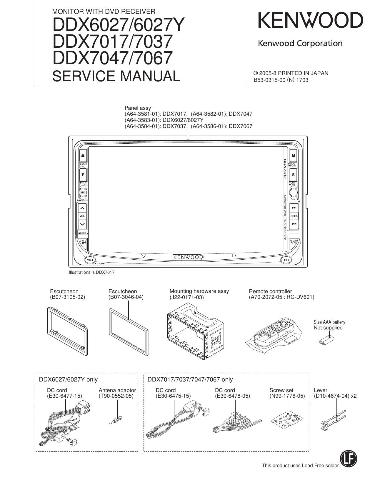
Kenwood DDX 6027 Y HU Service Manual

This is the 100 pages manual for Kenwood DDX 6027 Y HU Service Manual.
Read or download the pdf for free. If you want to contribute, please mail your pdfs to info@audioservicemanuals.com.

Page: 1 / 100
left right
Kenwood DDX 6027 Y HU Service Manual

Extracted text from Kenwood DDX 6027 Y HU Service Manual (Ocr-read)


Page 2

DDX6027/6027Y/7017
DDX7037/7047/7067

NOTES ON ASSEMBLING THE MECHANISM

1. Fasten Screw A so that the interval (a) will be about 5.2mm
and the interval (b) will be about 2.6mm (The interval (a)
can be measured using a pair of vernier calipers or similar
tools.)

2. Turn B so that Position (0) will come at about the center of
interval (d).

3. Then, play the test disc and fine tune A or B so that the jitter
value would be minimized.

Page 25

DDX6027/6027Y/7017
DDX7037/7047/7067

TEST MODE

Operation Specifications
0 Compatible Models for This Test Mode Specification

1Din GRA 1Din OSD 2Din GRA 2Din OSD M707
DSP Exist DSP Exist DSP None DSP Exist DSP None DSP None
K KVT-817DVD KVT-717DVD DDX8017 DDX7017 KVT-M707
Ft KVT-747DVD DDX7047
E KVT-827DVD KVT-727DVD KVT-627DVD DDX8027 DDX6027 KVT-M707
M KVT-837DVD KVT-737DVD DDX8037 DDX7037 -
X KVT-847DVD KVT-747DVD DDX8047 DDX7047 -
V KVT-867DVD KVT-767DVD DDX8067 DDX7067 -

- Depending on Din/Display Types in the table below, test mode specifications may differ from model to model.
In this specification, categorizing by 1DIN/2DIN and Graphic/OSD, M707, DSP, and destinations (K/R/E/M/X/V).

Model Din Type DSP Display Type
KVT-8x7DVD 1 DIN Exist Graphic
KVT-727DVD 1D|N Exist OSD
KVT-7x7/627DVD 1D|N None OSD
DDX80><7 2DIN Exist Graphic
DDX70x7/6027 2D|N None OSD
KVT-M707 1 DIN None OSD

x: Different in accordance with the region code

0 How to enter the test mode

There are two different ways to enter the test mode as shown

below.

1)Whi|e pressing [SRC key + ATT key] at the same time, reset
the unit.

2) Connect to Lx connector odd jigging for writing regions
(2DIN:When adjusting flicker)
Note1: The jig setting is arbitrary. Note that, however, there
are functions according the setting SW. (Region/SeriaI/Se-
curity/CPPM)
Note2: In the test mode, power supply is cut off after 30
minutes. (This is for making the operation possible without
Security input even when the security Is On.)

0 Adjustment items

Items to be adjusted after writing on the EEPROM on which
regions have been written.

As for the details of the adjustments, refer to each adjustment
item.

' Service Information/Serial Code writing

- Chroma adjustment

- Writing Touch Adjust values

- Screen position adjustment

- Panel mechanism position adjustment

- Writing Security Code (Other than K/R desinations)

0 How to clear the Security Code

In adjusting K/R destination units, if the unit starts up with

Security ON, the Security Code can be cleared in the follow-

ing manner. (Other than in Test Mode)

1) In the e Security ON condition, after resetting or turning
power ON after backup OFF, then the session starts with
Security Code Input screen.

2) With the attached remote control in the Audio SW selected
condition, input the code with the following procedure.
Procedure 1:K" input (Press Tenkey [5] 2 times)
Procedure 2: C" input (Press Tenkey [2] 3 times)
Procedure 3: A input (Press Tenkey [2] once)

Procedure 4: Q Input (Press Tenkey [7] 2 times)
Note: If a remote controller other than the attached is
used, Pressing Tenkey [7] twice will cause R" to be in-
put.
If a mistake Is made during Procedure 1~4 above, input
other remote controller Key. Then, start inputting again
from Procedure 1.

3) Security Code is complete when the input screen for the
Security Code is cleared

25

Page 47

DDX6027/6027Y/7017
DDX7037/7047/7067

PC BOARD (FOIL SIDE VIEW)

VIDEO UNIT X35-458/459X-10 C/3 (J76-0126-12)

x g g a n
I
2
4
x35 3/3
6
m 7
g: :2; Ex: :3
Rater to the schemaiic dia-
afiu E! if gram for the values of resis-
\ / tors and capacitors.

47

Page 98

DDX6027/6027Y/7017
DDX7037/7047/7067

PARTS LIST

DVD MECHANISM ASSY (X92-5130-00)

A N . . Desii- A N . . Desti-
Re1.No. g vev Paris No. Description nation Ret. No. g Vev Paris No. Description nation
8 2B D104769703 SLIDER D 3B N0976156705 MACHINE SCREW (M1 .4X1.6)
9 2A D1074771702 SLIDER E 1B N0976230705 MACHINE SCREW
10 2A D1074772703 SLIDER F 1A N1972192704 FLAT WASHER
11 2A D1074773713 SLIDER G 3B N0976133705 MACHINE SCREW (SERRATED)
12 2B D10»4774703 LEVER H 3A N0976134705 STEPPED SCREW (STEPPED)
13 2B D1074776723 ARM J 3A N0976203705 MACHINE SCREW
14 3A D1074795723 ARM K 3A N0976221r15 MACHINE SCREW (P 1.4X315)
17 3B D12»0638713 CAM L 2A N0976308705 MACHINE SCREW (P 1.4X4.5)
21 2B D1372298704 GEAR M 2A N1972183714 FLAT WASHER
22 2B D1372299704 GEAR
VM1 2A T4271321-05 MOTOR ASSY
23 2B D1372303704 GEAR VM2 3A T4271084r15 MOTOR ASSY
24 2B D1372305704 GEAR VM3 2B X9472000700 MOTORASSY (L0)
25 2B D1372306704 GEAR
26 1A D1372308704 GEAR 71 2A X94r2010700 ROLLER ASSY
27 1A D1372309704 GEAR VPU1 3B X9472020700 OPTICAL PICKUP ASSY
28 33 D1372316724 GEAR ASSY PANEL MECHANISM ASSY (D40-2201-15)
29 2B D1372300714 GEAR 601 2H A1075174728 CHASSIS CALKING ASSY
30 2A D1470799714 ROLLER
31 2A D14r1006704 ROLLER 602 3G D1074801738 SLIDER ASSY
33 3A D21 7242971 3 SHAFT 603 2G D1372324708 GEAR
604 2G D1372325708 GEAR
36 1A D3970259705 DAMPER 605 2G D1372326708 GEAR
607 2G D1470789708 ROLLER
37 2B 33970556705 LEAD WIRE
VFC1 2A E3970602705 FLAT CABLE 608 1G D1970650708 CLUTCH ASSY
38 3A F0771134r12 COVER 609 1H E3970671708 WIRING HARNESS
39 3A FOB-1930714 SHEET
40 3A F0971960704 SHEET 610 3G G0271480708 FLAT SPRING
44 3A F0971870704 SHEET
611 3H J2270118728 SLIDE RAIL
45 2B G0173192704 EXTENSION SPRING 612 3G J2270119728 SLIDE RAIL
46 2A G0173194724 EXTENSION SPRING 613 2G J2270120708 SLIDE RAIL
47 1B G0173195714 EXTENSION SPRING 614 2G J9071083708 GUIDE
48 2A G0173206724 TORSION COIL SPRING 615 2H J2270213708 MOUNTING HARDWARE (MOTOR)
49 2A G0173207r24 TORSION COIL SPRING
A 1H N0976147708 SCREW (M1 .7X4)
50 3A G0173209704 COMPRESSION SPRING B 1H N0976148708 SCREW (S2X2.3)
51 3A G02r1468704 FLAT SPRING D 3G N0976150708 SCREW
52 2B G02r1504r33 FLAT SPRING ASSY E 3G N0976151708 SCREW
53 1B G02r146-r24 FLAT SPRING F 1G N1972105714 CUT WASHER (1 .6X3.5X10.35)
54 3B G02r1488704 FLAT SPRING
PM1 1H T42r1100718 MOTOR ASSY
55 3A G0271473704 FLAT SPRING VR1 1H T9970448-05 SPEED DETECTOR
56 1B G1173614704 CUSHION (SR7S724P)
57 3B G1173622704 CUSHION (PORON)
58 2B J1170654r13 CLAMPER
59 1A J2270042r12 MOUNTING HARDWARE
60 1B J2270043r12 MOUNTING HARDWARE
61 3B J2270044703 MOUNTING HARDWARE
62 1A J2270103723 MOUNTING HARDWARE ASSY
63 2B J2270177r14 MOUNTING HARDWARE
64 1A J9071066741 GUIDE
65 1B 071067713 GUIDE
66 1B J9071087»32 GUIDE
67 1B 071088732 GUIDE
A 2A N09A6143705 MACHINE SCREW
B 1A N0976144705 MACHINE SCREW
C 3B N0976145705 MACHINE SCREW
E3 : DDX6027 E4 : DDX6027Y (Europe) A Indicates safety critical components
K1 :DDX7017 (North America)
98 X2 : DDX7047 (Australia) R1 : DDX7047 (Latin America)

C1 : DDX7067 (China) M2 : DDX7037 (Other Areas)